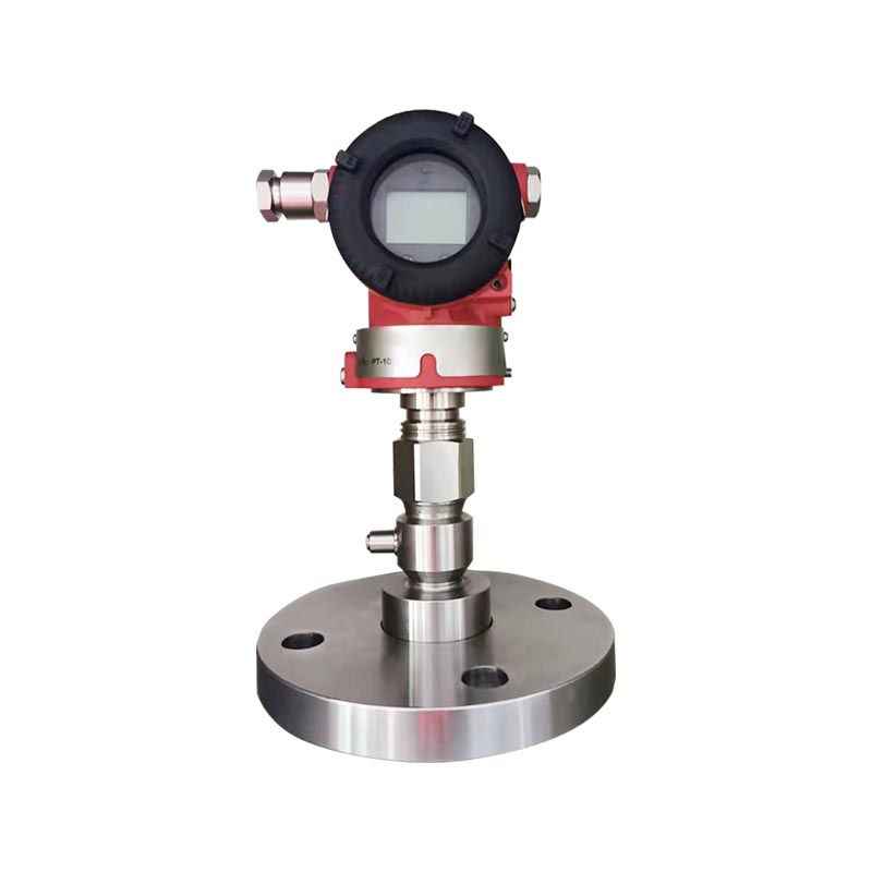
XG3051T Differential pressure/absolute pressure remote transmitter Manufacturers
Home / Product / Pressure instruments / Pressure transmitter / XG3051T Differential pressure/absolute pressure remote transmitter
  • XG3051T Differential pressure/absolute pressure remote transmitter
  • XG3051T Differential pressure/absolute pressure remote transmitter

XG3051T Differential pressure/absolute pressure remote transmitter

Product Introduction:
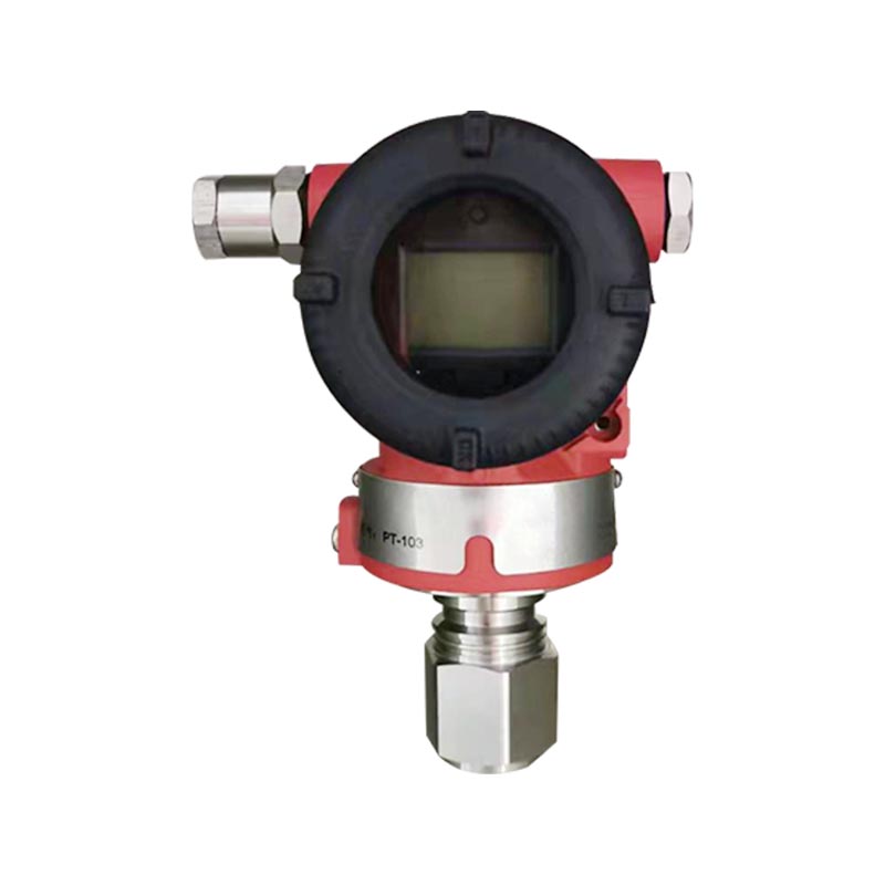
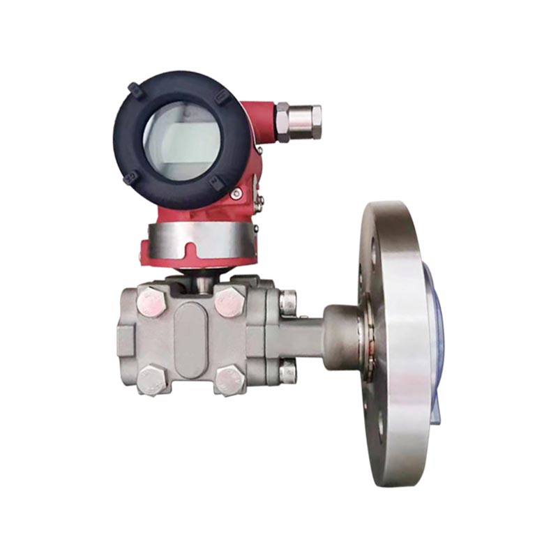
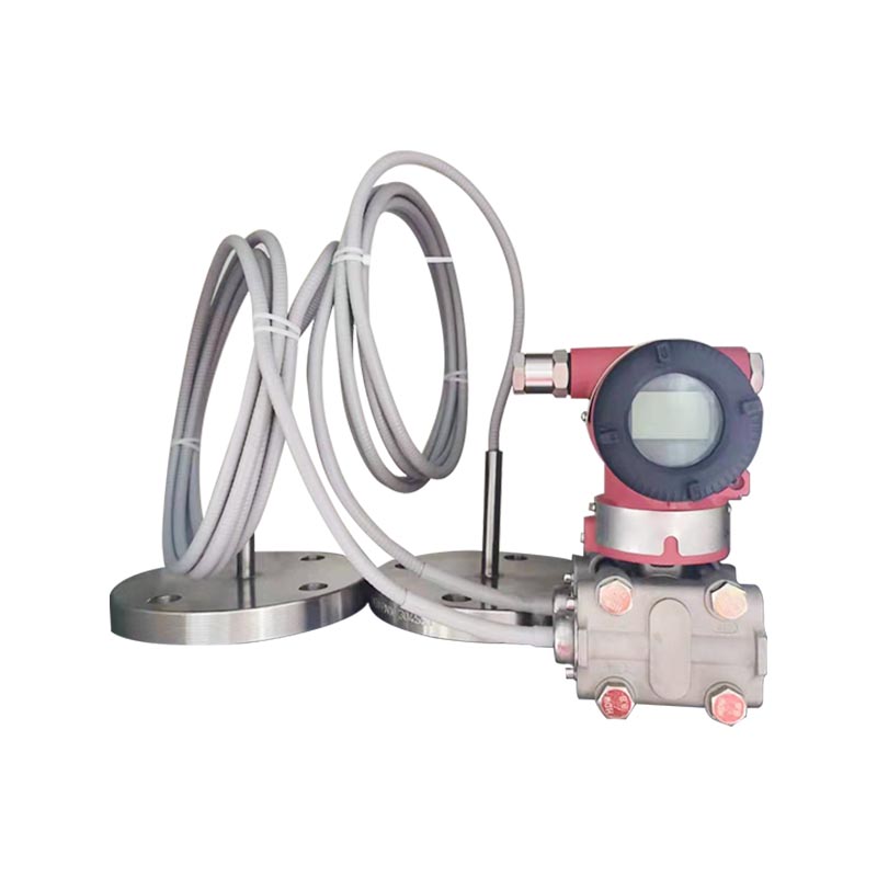
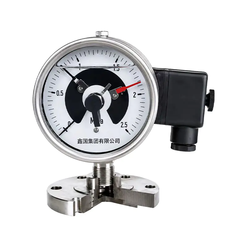
XG3051T intelligent remote pressure transmitter supports measuring gauge pressure and absolute pressure. It adopts a remote transmission capillary membrane isolation structure to isolate the measured medium from the transmitter body. It can cope with high viscosity, easy crystallization, easy solidification, strong corrosion, and high-temperature medium working conditions, preventing medium blockage and corrosion of sensors.
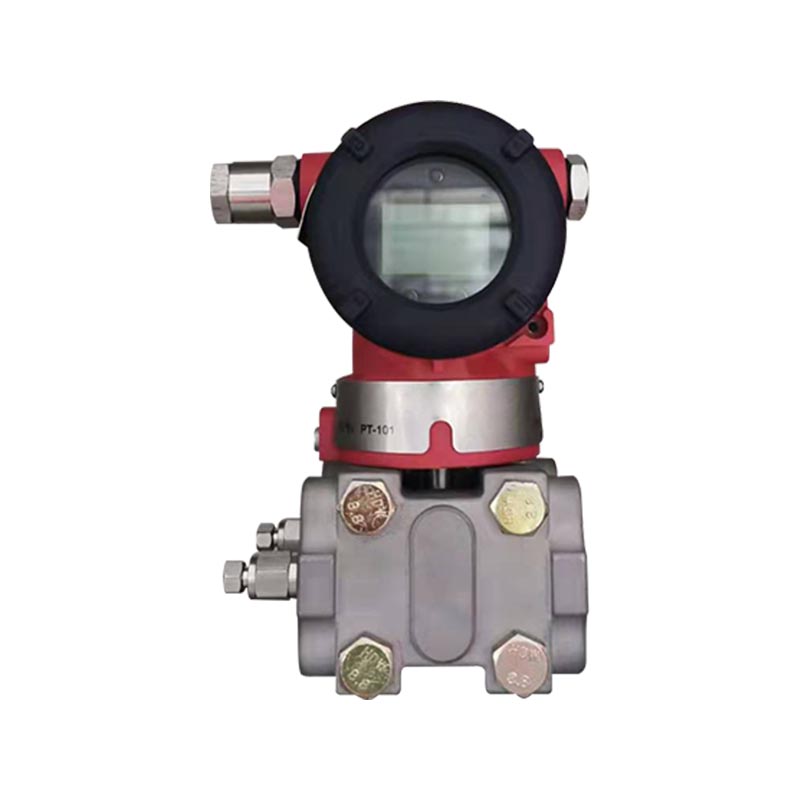
Output 4-20mA superimposed HART protocol digital signal, high accuracy, good long-term stability, supports on-site configuration calibration, optional on-site LCD, with explosion-proof protection, customizable diaphragm material, realizing long-distance transmission of pressure signals.

Applicable industries:
1. Petrochemical industry: pressure measurement of reaction vessels and storage tanks
2. Electricity: Boiler and heat pipe network pressure monitoring
3. Metallurgy: Pressure detection in the smelting process
4. Water treatment: sewage and chemical water treatment tank pressure
5. Pharmaceutical: Pressure control of pharmaceutical process tanks
6. Food and beverage: pressure measurement of viscous materials
7. Coal chemical industry: pressure detection of various process equipment
8. Paper making: pressure collection of pulp media

FAQ Input Output Response Time General Conditions Electrical Connections Model and Specification Code Table Dimensions
Q1: What operating conditions is the XG3051T remote transmitter suitable for?
A: Suitable for high viscosity, easy crystallization, easy solidification, strong corrosion, and high-temperature media. Through remote transmission membrane and capillary isolation, the medium is prevented from directly entering the transmitter body, preventing blockage and corrosion of the sensor. It supports two measurement modes: gauge pressure and absolute pressure.

Q2: How to choose between gauge pressure and absolute pressure?
A: Select gauge pressure for measuring relative atmospheric pressure. When measuring vacuum and negative pressure, absolute pressure should be selected as the reference for the working condition, and cannot be mixed; otherwise, there will be significant measurement errors.

Q3: What is the output signal? Can I connect to a HART handheld device?
A: Standard 4-20mA analog output, combined with HART digital protocol, supports on-site configuration, range modification, zero point calibration of HART controller, and can be connected to DCS and PLC systems.

Q4: How to choose the material for remote transmission film?
A: Conventional 316L stainless steel; for strong corrosive media, Hastelloy alloy and tantalum film can be selected, and the composition and temperature of the media can be provided when ordering.

Measurement parameters: gauge pressure, exothermic pressure, liquid level.

Measurement Range
Gauge Pressure Remote Transmitter Lower limit: starting from -100%URL (continuously adjustable)
Upper limit: up to +100%URL (continuously adjustable)
Absolute Pressure Remote Transmitter Lower limit: starting from 0~100%URL (continuously adjustable)
Upper limit: up to +100%URL (continuously adjustable)

Measurement Range

Table 1 — Relationship between Range Code and Range
Range Code Minimum Range Maximum Range Rated Pressure (Max)
C 6 kPa 40 kPa Rated pressure of the level flange
D 25 kPa 250 kPa
F 30 kPa 3 MPa
G 1 MPa 10 MPa
H 2.1 MPa 21 MPa
I 4 MPa 40 MPa
L 6 kPa abs 40 kPa abs
M 25 kPa abs 250 kPa abs
O 30 kPa abs 3 MPa abs
Table 2 —  Comparison Table of Remote Flange and Minimum Range
Flange Type Nominal Diameter Min/Max Range Maximum Capillary Length
Flat Type DN 25/1" 160kPa/25MPa 10m
DN 50/2" 10kPa/10MPa 12m
DN 80/3" 6kPa/10MPa 16m
DN 4" 6kPa/3MPa 16m
Inserted Type DN 50/2" 16kPa/10MPa 10m
DN 80/2" 6kPa/10MPa 16m
DN 4" 6kPa/3MPa 16m
Thread-mounted Remote Type Outer Diameter 109mm 160kPa/25MPa 10m

The minimum range of the gauge pressure / absolute pressure remote transmitter shall be the larger value of the minimum ranges specified in Table 1 and Table 2. The adjusted range shall not be less than the minimum range.
The maximum range of the gauge pressure / absolute pressure remote transmitter shall be the smaller value between the maximum range of the transmitter body and the rated pressure of the remote flange.

Output Signal
2-wire, 4–20 mA DC HART output, digital communication; the HART protocol is superimposed on the 4–20 mA DC signal.
Output Signal Limits: Imin = 3.9 mA, Imax = 20.5 mA

Alarm Current (Configurable Mode)
Low Alarm Mode (Minimum) 3.7 mA
High Alarm Mode (Maximum) 21 mA
No Alarm Mode (Hold) Holds the valid current value before a fault
Standard Setting of Alarm Current High Alarm Mode


The damping constant of the amplifier component is 0.1 s; the time constant of the sensor and remote seal flange ranges from 0.2 ~ 6 s, depending on the sensor range, range ratio, capillary length, and viscosity of the fill fluid.
The additional adjustable time constant ranges from 0.1 ~ 60 s.

Installation Conditions
Gauge / absolute pressure remote transmitters without capillary tubes can be mounted directly via the remote flange. Position deviation will cause a correctable zero shift. The electronics housing can rotate up to 360°, and the set screw can secure it in any position.

The gauge / absolute pressure remote flange connects to mating flanges complying with ANSI/DIN standards. Such mating flanges shall be equipped with soft gaskets and mounting bolts and nuts (bolts and nuts are optional for users).

For gauge / absolute pressure remote transmitters with capillary tubes: if the remote seal assembly is installed below the transmitter body, the maximum height difference between the remote seal assembly and transmitter body shall be less than 5 m. When the operating pressure is below 100 kPa absolute, install the transmitter body below the remote seal assembly.

The minimum bending radius of the capillary tube is 75 mm. No coiling is allowed!

Environmental conditions

Ambient Temperature
Minimum Depends on fill fluid
Maximum 85 ℃
With LCD and FKM seal -20 ~ 65 ℃
Storage / Transport Temperature
Minimum Depends on fill fluid
Maximum 85 ℃
Relative Humidity 0 ~ 100 %
Shock Resistance
Acceleration 50 g
Duration 11 ms
Vibration Resistance 2 g up to 500 Hz
Electromagnetic Compatibility (EMC) See Table 4 "EMC Appendix" on the next page

Process medium limit temperature limit
Medium temperature:-30~400°C

Table 3 Relationship of Fill Fluid, Operating Temperature and Minimum Operating Pressure
Fill Fluid Silicone Oil (S) High-Temp Silicone Oil (H) Ultra-High-Temp Silicone Oil (U) Vegetable Oil (V)
Density @25℃ 960 kg/m³ 980 kg/m³ 1020 kg/m³ 937 kg/m³
Operating Temperature Range -30 ~ 200℃ -10 ~ 350℃ -10 ~ 400℃ 0 ~ 250℃
Temperature Operating Pressure Range (kPa absolute)
20℃ >10 >10 >10 >25
100℃ >25 >25 >25 >50
150℃ >50 >50 >50 >75
200℃ >75 >75 >75 >100
250℃ >100 >100 >100
350℃ >100 >100
400℃ >100

Note: Special attention should be paid to any values exceeding the above temperature and pressure range; these can be met through
special design.

Item Specification
Transmitter Body Pressure Limit Vacuum to maximum pressure
Remote Flange Rated Pressure ANSI: 150 psi ~ 600 psi
DIN: PN 1.6 MPa ~ PN 10 MPa
Weight DN 50/2": approx. 7 ~ 10 kg
DN 80/3": approx. 8 ~ 11 kg
DN 4": approx. 9 ~ 12 kg
Explosion-Proof Performance NEPSI flameproof: Ex dⅡC T6
NEPSI intrinsic safety: Ex iaⅡC T4
Permitted Operating Temperature -40 ℃ ~ 65 ℃

Power and Load Conditions
Power supply voltage is 24V
R≤(Us-12V) /Imax kQ 2
where Imax=23 mA
Maximum power supply voltage: 42VDC
Minimum power supply voltage:12VDC,15VDC(backlight LCD display)
Digital communication load range: 250~600Q

Item Specification
Material
Measuring Capsule Stainless Steel 316L
Diaphragm Stainless Steel 316L, Hastelloy C, Tantalum
Process Flange Stainless Steel 304
Fill Fluid Silicone Oil, High-Temp Silicone Oil, Ultra-High-Temp Silicone Oil, Vegetable Oil
Transmitter Housing Aluminum Alloy with Epoxy Coating
Housing Gasket Nitrile Rubber (NBR)
Nameplate Stainless Steel 304
Electrical Connection M20×1.5 cable gland; terminals suitable for 0.5 ~ 2.5 mm² conductors
Process Connection Remote seal flange complies with ANSI or DIN standard. Direct mounting available; refer to the dimension drawing
Housing Protection Class IP67
Table 4 EMC Annex
No. Test Item Basic Standard Test Condition Performance Level
1 Radiated Emission (Enclosure) GB/T 9254-2008 Table 5 30MHz ~ 1000MHz Pass
2 Conducted Emission (DC Power Port) GB/T 9254-2008 Table 1 0.15MHz ~ 30MHz Pass
3 Electrostatic Discharge (ESD) Immunity GB/T 17626.2-2006 4kV (Contact), 8kV (Air) B
4 Radiated RF Electromagnetic Field Immunity GB/T 17626.3-2006 10V/m (80MHz~1GHz) A
5 Power Frequency Magnetic Field Immunity GB/T 17626.8-2006 30A/m A
6 Electrical Fast Transient Burst Immunity GB/T 17626.4-2008 2kV (5/50ns,5kHz) B
7 Surge Immunity GB/T 17626.5-2008 1kV (Line to Line) B
2kV (Line to Earth) (1.2us/50us)
8 Conducted Disturbance Immunity induced by RF fields GB/T 17626.6-2008 3V (150KHz ~ 80MHz) A

Notes:
(1) Performance Level A: Performance remains within the limits of technical specifications during the test.
(2) Performance Level B: Temporary degradation or loss of function/performance may occur during the test, but the unit can recover automatically. The actual operating status and stored data remain unchanged.

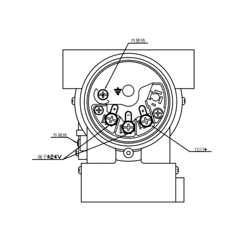
Figure 6: Electrical Connection Diagram
100006

Note: The quick interface function is equivalent to the signal terminal.

1 Basic Type Gauge/Absolute Pressure Remote Transmitter — Flange Selection
10 Basic Type Gauge/Absolute Pressure Remote Seal Assembly
1 RN- Direct installation type, no capillary tube
RS- With capillary tube
20 Process Connection Nominal Diameter Seal Face Type Diaphragm / Seal Face Material
A DN50 DIN2501 Type E DIN2526 Stainless Steel 316L
B DN50 DIN2502 Type E DIN2526 Hastelloy C
C DN50 DIN2503 Type E DIN2526 Tantalum
H DN80 DIN2504 Type E DIN2526 Stainless Steel 316L
I DN80 DIN2505 Type E DIN2526 Hastelloy C
G DN80 DIN2506 Type E DIN2526 Tantalum
D DN2" ANSI B 16.5 RF ANSI B16.5 Stainless Steel 316L
E DN2" ANSI B 16.5 RF ANSI B16.5 Hastelloy C
F DN2" ANSI B 16.5 RF ANSI B16.5 Tantalum
K DN3" ANSI B 16.5 RF ANSI B16.5 Stainless Steel 316L
L DN3" ANSI B 16.5 RF ANSI B16.5 Hastelloy C
M DN3" ANSI B 16.5 RF ANSI B16.5 Tantalum
N DN4" ANSI B 16.5 RF ANSI B16.5 Stainless Steel 316L
O DN4" ANSI B 16.5 RF ANSI B16.5 Hastelloy C
P DN4" ANSI B 16.5 RF ANSI B16.5 Tantalum
Q DN100 DIN2501 Type E DIN2526 Stainless Steel 316L
S DN100 DIN2501 Type E DIN2526 Hastelloy C
T DN100 DIN2501 Type E DIN2526 Tantalum
30 Rated Pressure Flange Pressure Standard
1 PN 1MPa / 4MPa DIN2501
2 PN 6.4MPa DIN2501
3 PN 10MPa DIN2501
6 150 psi ANSI B16.5
7 300 psi ANSI B16.5
8 600 psi ANSI B16.5
Description
40 F Flat type
H Inserted type, Stainless Steel 316L, insertion length 50 mm
I Inserted type, Stainless Steel 316L, insertion length 100 mm
G Inserted type, Stainless Steel 316L, insertion length 150 mm
L Inserted type, Hastelloy C, insertion length 50 mm
M Inserted type, Hastelloy C, insertion length 100 mm
N Inserted type, Hastelloy C, insertion length 150 mm
Z Special (custom made)
50 Fill Fluid Operating Temp. Range
S Silicone Oil -30 ~ 200 ℃
H High-Temperature Silicone Oil -10 ~ 350 ℃
U Ultra-High-Temperature Silicone Oil -10 ~ 400 ℃
V Vegetable Oil 0 ~ 250 ℃
F Fluorinated Oil -30 ~ 260 ℃
L Ultra-Low-Temperature Fill Fluid -100 ~ 100 ℃
Z Ultra-High-Temperature Fill Fluid 10 ~ 600 ℃
60 Capillary Length
0 Without capillary, direct mounting type
1 1 m
2 2 m
3 3 m
4 4 m
5 5 m
6 6 m
7 7 m
8 8 m
9 9 m
10 10 m
11 11 m
12 12 m
… …
70 Capillary Part Feature
N None
P Capillary with PVC protective layer
80 Diaphragm Face Form of Wetted Process Flange
N None
1 FEP (fluorinated ethylene propylene) coated on 316L (temp. ≤ 180 ℃)
2 PFA (perfluoroalkoxy) coated on 316L (temp. ≤ 260 ℃)
3 PTFE membrane pasted on diaphragm (flat type only)
4 FEP coated on 316L (temp. ≤ 180 ℃) (inserted type only)
5 PFA coated on 316L (temp. ≤ 260 ℃) (inserted type only)
6 Vacuum-proof treatment


2 Options for Pressure/Absolute Pressure Remote Seal Assembly with Internal Diaphragm [6]
10 Remote Seal Assembly with Internal Diaphragm
RN- Direct mounting type, without capillary
RS- With capillary
20 Process Connection Nominal Diameter Seal Face Type Diaphragm / Seal Face Material
U DN25 DIN 2501 Type D DN2526 Stainless Steel 316L Stainless Steel 316L
V DN25 DIN 2501 Type D DN2526 Hastelloy C Hastelloy C
W DN25 DIN 2501 Type D DN2526 Tantalum Tantalum
X DN1" ANSI B 16.5 RF Type ANSI B 16.5 Stainless Steel 316L Stainless Steel 316L
Y DN1" ANSI B 16.5 RF Type ANSI B 16.5 Hastelloy C Hastelloy C
Z DN1" ANSI B 16.5 RF Type ANSI B 16.5 Tantalum Tantalum
30 Rated Pressure Flange Standard Stainless Steel 316L
1 PN 1MPa / 4MPa DIN 2501
2 PN 6.3MPa / 10MPa DIN 2501
3 PN 16MPa DIN 2501
4 PN 25MPa DIN 2501
5 150 psi ANSI B 16.5
6 300 psi ANSI B 16.5
7 600 psi ANSI B 16.5
8 1500 psi ANSI B 16.5
40 Fill Fluid Temperature Range
S Silicone Oil -30 ~ 200℃
H High-Temperature Silicone Oil -10 ~ 350℃
V Vegetable Oil 0 ~ 250℃
F Fluorinated Oil -30 ~ 260℃
50 Description
1 1 m
2 2 m
3 3 m
4 4 m
5 5 m
6 6 m
… …
60 Description
N None
P Capillary with PVC protective layer
70 Description
N None
3 Diaphragm pasted with PTFE membrane (temperature ≤200℃)
6 Vacuum-proof treatment
80 Code Description
1 PTFE (Polytetrafluoroethylene)
2 Stainless Steel 316
3 Hastelloy C
4 Tantalum

Note 6: When selecting pressure/vacuum remote transmission seals for devices with internal diaphragms, first complete the selection of the XG3051T gauge/vacuum transmitter, and select option R from row 40 in the XG3051T options table.

3 Screw Mounted Gauge/Absolute Pressure Remote Seal Assembly Selection [10]
10 Screw Mounted Gauge/Absolute Pressure Remote Seal Assembly
RTW- With capillary
20 Description
U Stainless Steel 316L
V Hastelloy C
W Tantalum
30 Flushing / Vent Hole
1 None
0 With hole
40 Fill Fluid Temperature Range
S Silicone Oil -30 ~ 200℃
H High-Temperature Silicone Oil -10 ~ 350℃
U Ultra-High-Temperature Silicone Oil -10 ~ 400℃
V Vegetable Oil 0 ~ 250℃
F Fluorinated Oil -30 ~ 260℃
L Ultra-Low-Temperature Fill Fluid -100 ~ 100℃
Z Ultra-High-Temperature Fill Fluid 10 ~ 600℃
50 Description
1 1 m
2 2 m
3 3 m
4 4 m
5 5 m
6 6 m
50 8 8 m
… …
Capillary Part Feature
60 N None
P Capillary with PVC protective layer
70 Wetted Flange Diaphragm Face Form
N None
P Vacuum-proof treatment

Note 10: When selecting a threaded-mounted remote control flange sealing device, first complete the selection for the XG3051T gauge pressure/absolute pressure transmitter body section, and select option R for the remote transmission in row 40 of the XG3051T options table.

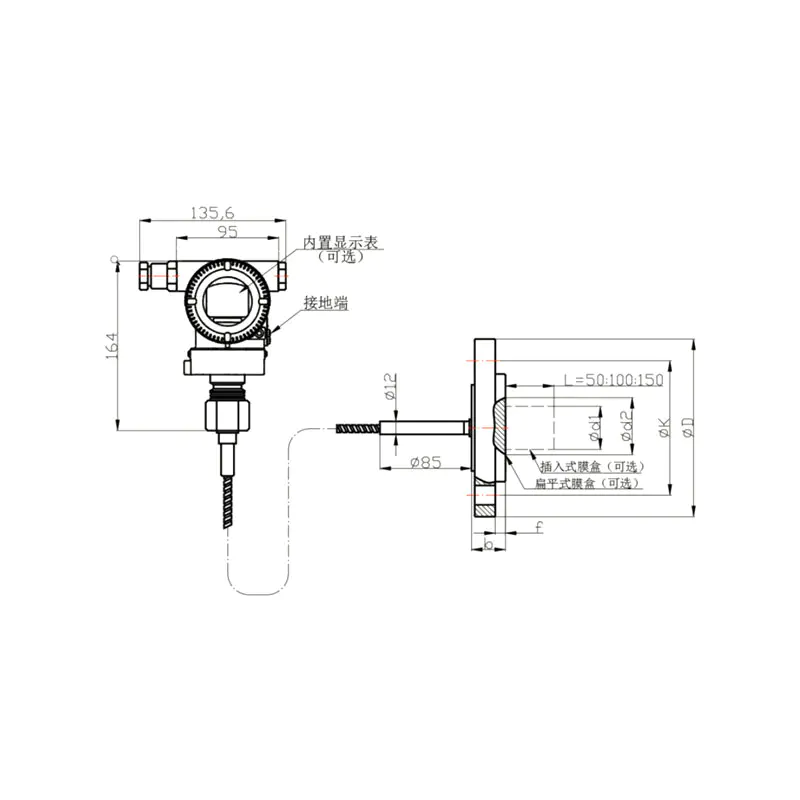
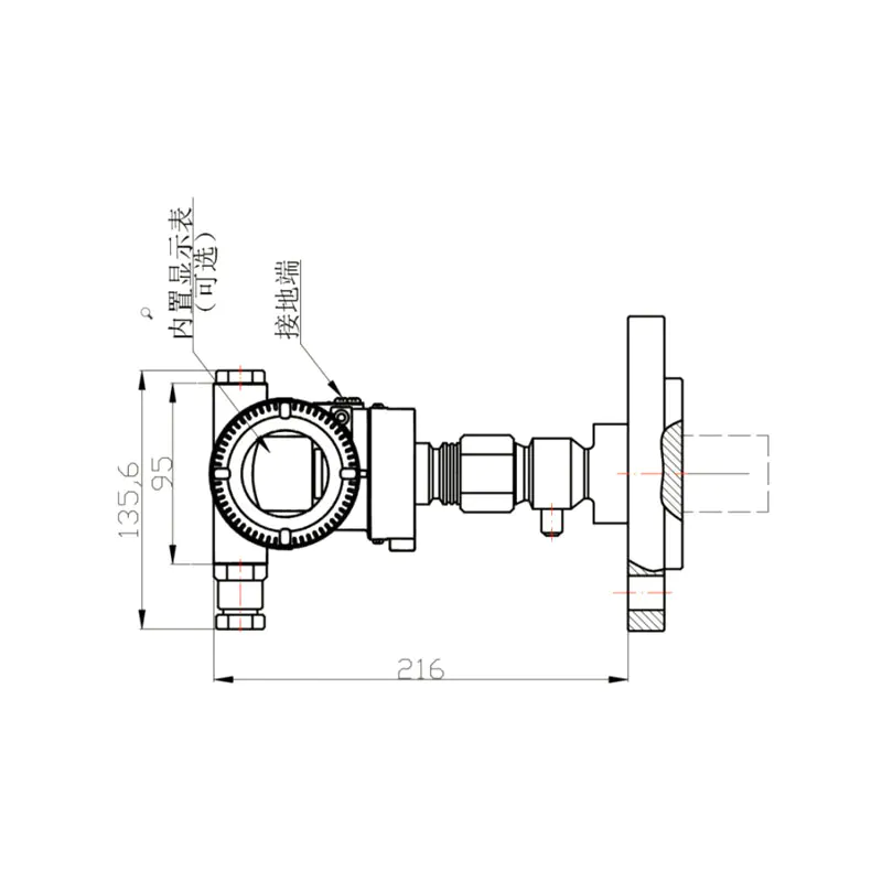
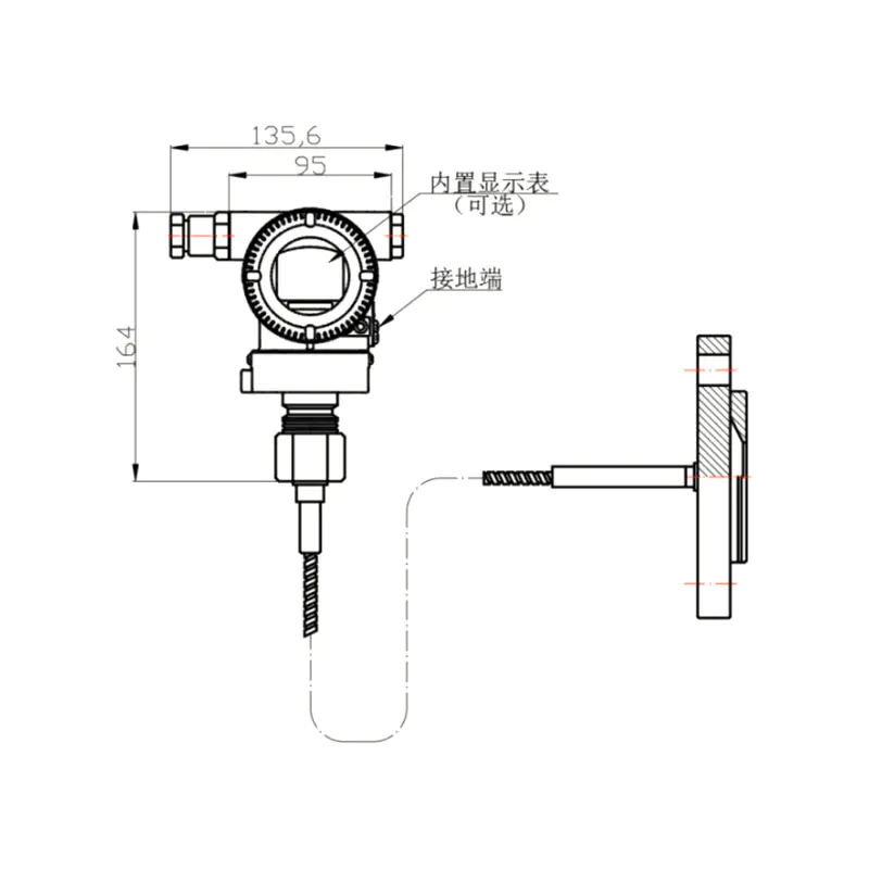
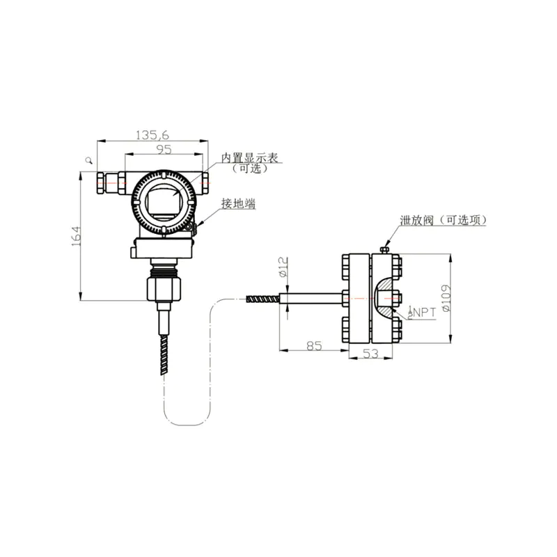
Figure 1. Basic Type Remote Sealing Device Diagram (RS Type) Figure 2. Basic Type Remote Sealing Device Direct Mounting Diagram (RN Type)
100051-KqgD 100042-3GnN
Nominal Diameter Rated Pressure ΦD ΦK Φd1 (Inserted) Φd2 (Flat) Φd3 t b Bolts (Qty) Bolts (Thread)
DN50(Seal face DIN 2526-E, Flange DIN 2501) PN1.6/4 MPa 165 125 48.3 57 102 3⁺⁰·⁵ 20 4 M16
PN6.4 MPa 185 135 48.3 57 102 3⁺⁰·⁵ 26 4 M20
PN10 MPa 195 145 48.3 57 102 3⁺⁰·⁵ 28 4 M20
DN80(Seal face DIN 2526-E, Flange DIN 2501) PN1.6/4 MPa 200 160 76 75 138 3⁺⁰·⁵ 24 8 M16
PN6.4 MPa 215 170 76 75 138 3⁺⁰·⁵ 28 8 M20
PN10 MPa 230 180 76 75 138 3⁺⁰·⁵ 32 8 M24
DN2"(ANSI B16.5 RF) 150 psi 152.4 120.6 48.3 57 92.1 3⁺⁰·⁵ 17.4 4 M18
300 psi 165.1 127 48.3 57 92.1 3⁺⁰·⁵ 20.6 8 M18
600 psi 165.1 127 48.3 57 92.1 6.35 31.75 8 M18
DN3"(ANSI B16.5 RF) 150 psi 190.5 152.4 76 75 127 3⁺⁰·⁵ 22.2 4 M16
300 psi 209.5 168.3 76 75 127 3⁺⁰·⁵ 27 8 M20
600 psi 209.5 168.3 76 75 127 6.35 38.05 8 M20
DN4"(ANSI B16.5 RF) 150 psi 229 191 89 89 157 3⁺⁰·⁵ 30 8 M18
300 psi 255 200 89 89 157 3⁺⁰·⁵ 32 8 M18

Note: Users can optionally install bolts and nuts.

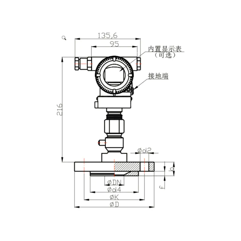
Figure 3: Remote Sealing Device with Internal Diaphragm (US Type) Figure 4: Direct installation diagram of remote control seal device with internal diaphragm (UN type) Figure 5:Threaded Installation Type Remote Control Sealing Device Diagram (RTW Type)
100033 100015 100024
Table 6 Structural Dimensions of Remote Seal Assembly with Internal Diaphragm for DIN 2501 Connection
DN PN Dimensions, mm Weight(kg)
D K d4 b f H d2 G2
25 1MPa / 4MPa 115 85 68 22 2 – 14 – 1.5
25 6.3MPa / 10MPa 140 100 68 24 2 52 – 4×M16 3.2
16MPa 140 100 68 24 2 52 – 4×M16 3.6
25MPa 150 105 68 28 2 96 – 4×M20 4
Table 7 Structural Dimensions of Remote Seal Assembly with Internal Diaphragm for ANSI B 16.5 Connection
DN psi Dimensions, mm G₂ UNC Weight (kg)
D K d2 d4 b f H
1" 150 110 79.5 16 51 22 2 – – 1.4
300 125 89 20 51 22 2 – – 1.7
1" 600 125 89 – 51 25 7 53 4×5/8" 3.6
1500 150 101.5 – 51 36 7 64 4×7/8" 4

Xinguo Group Co., Ltd.
ABOUT US Xinguo Group Co., Ltd.
Xinguo Group Co., Ltd. is a high-tech enterprise with subsidiaries including Anhui Xinguo Instrument Co., Ltd., Anhui Xinguo Alloy Co., Ltd., Anhui Xinguo Cable Co., Ltd. and Anhui Xinguo Precious Metals Co., Ltd. Founded in 1997, the Group is located in Tianchang City, Anhui Province — a National Civilized City. It has a registered capital of 118 million RMB, covers a land area of over 150 mu and a building area of 60,000 square meters. The company currently has more than 300 employees, among whom over 50 are professional and technical personnel including senior engineers, engineers and assistant engineers.
The Group is a China Custom XG3051T Differential pressure/absolute pressure remote transmitter Manufacturers and XG3051T Differential pressure/absolute pressure remote transmitter Supplier, mainly engages in the R&D, production and sales of temperature instruments, pressure instruments, level instruments, flow instruments and digital display instruments. Its product portfolio also encompasses power cables, control cables, compensation cables, computer cables, signal cables, MI heating cables, mineral insulated cables, electric heat tracing tapes, cable trays and accessories, high and low voltage distribution equipment, complete automation control systems, instrument valves, pipeline valves and fittings, glass instruments and laboratory equipment. We also supply platinum-rhodium wires, precision alloys and complete mechanical equipment, while providing supporting processing, manufacturing, sales and technical services. Additionally, we deal in professional instrument materials, alloy materials and precious metals. Our products are widely applied in power, petroleum, chemical, metallurgy, building materials, machinery, food, aerospace, new energy and other industrial sectors, as well as scientific research and education fields.
Anhui Xinguo Alloy Co., Ltd. is dedicated to manufacturing a full range of precision alloy materials and serves as a council member of the Instrument Materials Branch of China Instrument & Control Society. Its flagship products cover thermocouple alloy wires (K, N, E, J, T types), thermocouple compensation alloy wires (KX, EX, NX, JX, TX, KCA, KCB, NC, SC), high-resistance heating alloys, precision resistance alloys, heating resistance alloys, pure nickel wires, manganese-copper alloys and Monel alloys. These products are extensively used in aviation, petroleum, chemical engineering, machinery manufacturing, power and energy industries.

  • 0year

    Founded in

  • 0+mu

    Cover an area of

  • 0+

    Experienced employees

  • 0㎡

    Building area

NEWS Provide You With The
Latest Enterprise and Industry News