The first sign that something is wrong with a thin film RTD is rarely a dramatic failure. It is a slow disagreement with a neighbouring sensor, a reading that creeps during a heat-up cycle, or a batch trend that no longer matches the recipe. In one case, a food processor replaced an assembly in a pasteuriser jacket three times in eighteen months, convinced the element was at fault. The real cause was a two-wire connection that added roughly 2.6 ohms of lead resistance to a Pt100 circuit, which is about 6.8 degrees of error the calibration loop had quietly masked at commissioning and then lost when the terminal block was rewired.
Thin film RTD elements are the right default for most industrial temperature measurement between about -70 °C and 400 °C, especially where space is tight, vibration is present, or hundreds of sensors are needed at a sensible unit price. They are the wrong choice above roughly 500 °C, in applications where long-term stability matters more than size, and in any circuit where the wiring has not been thought through. The rest of this guide explains how to tell those situations apart and what to demand from a manufacturer before you place an order.
A thin film RTD is a platinum resistance element made by depositing a very thin platinum layer onto a ceramic substrate, patterning it into a meander, and laser trimming it so the resistance equals 100 ohms, 500 ohms or 1000 ohms at 0 °C. Because the sensing layer is thin and the substrate is small, the element reacts quickly, tolerates vibration reasonably well, and can be produced in high volumes with consistent tolerances. Those three characteristics explain almost every design decision you will make around them.
It is worth stating the working principle plainly, because it drives every practical decision later. Platinum resistance rises in a predictable, near-linear way as temperature increases, roughly 0.385 ohms per degree for a 100 ohm element and 3.85 ohms per degree for a 1000 ohm element. A transmitter or meter passes a small, stable current through the element, measures the resulting voltage or resistance, and converts it into a temperature. Anything that adds resistance to that loop, whether a lead wire, a corroded terminal, or a poor weld, is read as extra temperature.
A thin film element is built up in layers. An alumina substrate provides mechanical support and electrical insulation. A platinum film, typically well under two micrometres thick, is deposited on it by sputtering. Photolithography and etching shape that film into a long, narrow track so the resistance is high enough to be useful. A laser then trims the track until the element measures the target resistance at the reference temperature, usually trimming to within a small fraction of a percent. A glass or epoxy passivation layer protects the film, and two or four lead wires are attached, often with a spot weld or a conductive bond.
The whole element might measure two millimetres by two millimetres, or five millimetres by ten, with a thickness under a millimetre. That small thermal mass is why a bare thin film element can reach ninety percent of a step change in a couple of seconds, where a wire-wound element of similar nominal accuracy may take several times longer. It is also why thin film elements handle vibration and shock better: there is no fine coil to shift, sag or short against itself.
The trade-off appears at high temperature. A wire-wound element suspends a coil of very pure platinum wire in a ceramic former, so the sensing metal is continuous, stress-free, and can be annealed. A thin film element is bonded to a substrate, and the mismatch in thermal expansion between platinum and alumina creates mechanical stress every time the element heats and cools. That stress accumulates. Below about 400 °C the effect is modest and predictable; above 500 °C it dominates, and drift accelerates.
| Feature | Thin film RTD | Wire-wound RTD |
|---|---|---|
| Sensing structure | Platinum film on a ceramic substrate, laser trimmed | Platinum coil wound on a ceramic former |
| Common element size | 2 x 2 mm up to 5 x 10 mm | 3 x 10 mm and larger |
| Response time, bare element | Often 1 to 3 seconds for t90 | Often 3 to 10 seconds for t90 |
| Vibration and shock | Good, low mass, no moving coil | Weaker, the coil can shift or short |
| Practical upper range | Around 400 to 500 °C in continuous service | 600 to 850 °C depending on construction |
| Stability at high temperature | Acceptable below 400 °C, drifts faster above | Better near the top of the range |
| Unit cost at volume | Lower | Higher |
| Resistance options | 100, 500 and 1000 ohms widely available | 100 ohms dominant |
| Handling | Brittle substrate, avoid bending forces | Fragile wire, avoid tension and sharp bends |
Where does that leave a buyer? If the process runs below 400 °C, if the probe must fit into a small thermowell, if the machine vibrates, or if the loop needs a fast response for control, thin film is the sensible engineering answer. If the process sits at 600 °C in a furnace, or the sensor is a reference standard used to calibrate others, a wire-wound element is still the better tool.
The element is only half the measurement. The other half is the circuit that connects it to the instrument, and this is where most day-to-day accuracy is lost.
A Pt100 changes by about 0.385 ohms per degree. A Pt1000 changes by about 3.85 ohms per degree, ten times more. That higher sensitivity is why Pt1000 elements tolerate long two-wire runs better: one ohm of lead resistance is roughly 2.6 °C of error on a Pt100 but only about 0.26 °C on a Pt1000. The penalty is that Pt1000 elements need lower excitation current to avoid self-heating, are slightly more sensitive to electrical noise, and usually cost a little more. For panel-mounted instruments short on space, multi-sensor machines, and two-wire loops, Pt1000 is often the practical answer. For high-accuracy four-wire measurement, Pt100 remains the common choice.
Consider a realistic example. Two conductors of 0.5 mm² copper, each ten metres long, add roughly 0.7 ohms in total at room temperature. On a Pt100 that is about 1.8 °C of offset. Use thinner 0.22 mm² cable and a thirty-metre run and the added resistance can exceed four ohms, which is more than ten degrees on a Pt100. The same cable on a Pt1000 adds less than one degree.
Three-wire connection assumes the two current-carrying leads have identical resistance. It cancels most of the lead error when they do. When they do not, the residual error is real: a mismatch of 0.1 ohm between cores is about 0.26 °C on a Pt100. That mismatch grows with temperature if the cores follow different routes, which is one reason to keep the cable as a single matched run and avoid mixing cores from different drums.
| Connection | Conductors | Effect of lead resistance | Typical use |
|---|---|---|---|
| Two-wire | 2 | Fully added to the reading; 1 ohm equals about 2.6 °C on Pt100, 0.26 °C on Pt1000 | Short cable runs, Pt1000, indication only |
| Three-wire | 3 | Cancelled when cores match; 0.1 ohm mismatch equals about 0.26 °C on Pt100 | Most industrial transmitters and panel meters |
| Four-wire | 4 | Almost completely removed, independent of cable length | Laboratories, narrow spans, high accuracy |
If you are specifying an assembly with a head-mounted transmitter, check whether the transmitter supports three-wire or four-wire input, and whether the terminal block actually has the matching number of terminals. It is surprisingly common to find a four-wire element wired into a three-wire transmitter because the terminal labels were misread.
The class printed on a datasheet is a limit, not a promise about your process. It describes how far the element may deviate from the standard resistance-temperature curve at a defined temperature, and it says nothing about how the assembly behaves once it is installed in a thermowell.
The chart below shows the four common tolerance classes as defined for platinum resistance elements at the ice point. Reading it as a size comparison rather than a set of bare numbers makes the practical gap clearer: Class C allows six times the deviation of Class AA.
Permitted deviation at 0 °C by tolerance class
Three things matter when you read that chart against a real specification. First, the class limits are usually quoted at the ice point, and the allowance grows with temperature. A Class A element is allowed roughly 0.15 plus 0.002 times the absolute temperature, which is close to one degree at 400 °C. A Class B element is allowed roughly 0.30 plus 0.005 times the absolute temperature, which is over two degrees at the same point.
Second, the class applies to the element, not to the finished probe. Once the element sits inside a stainless steel sheath with a mineral-insulated cable, the assembly adds its own error from stem conduction, immersion depth and sheath fit. A Class A element in a poorly immersed probe can easily deliver Class C performance.
Third, on a real production line the difference between classes is often less important than repeatability. A Class B thin film RTD that returns to within 0.1 °C after every cycle is more useful than a Class AA element that drifts in an unstable installation. When you buy a sheathed or head-mounted assembly, ask the manufacturer for the calibration data at two or three temperatures, not just the class printed on the label.
Datasheets often quote a wide operating range, sometimes from -200 °C to 600 °C. That range describes what the element survives, not what it will do for years on end. In continuous service, most thin film elements are comfortable from -70 °C to about 400 °C, with excursions higher if they are infrequent. Above that, the accumulation of thermal stress in the film speeds up drift, and the failure mode is usually a slow upward shift in resistance rather than an open circuit.
Drift is best expressed as a rate under defined conditions, so treat any single number with caution. A useful question for a supplier is how the element was qualified: how many hours at what temperature, how many thermal cycles between which limits, and what the measured change in resistance was at the ice point afterwards. A supplier who can show the test method and the sample size is more credible than one who quotes a stability figure without context.
Self-heating is the other quiet error. It comes from the excitation current the instrument pushes through the element. For a Pt100 at 1 mA the dissipated power is about 0.1 milliwatts; for a Pt1000 at the same current it is about 1 milliwatt. In still air a small element may rise roughly 0.2 °C per milliwatt, so a Pt1000 driven at 1 mA could read up to two tenths of a degree high for that reason alone. Inside a thermowell with decent thermal contact the effect is much smaller, which is why self-heating is rarely visible in a well-installed probe and frequently visible in a bare element hanging in air.
Response time follows the same logic. A bare two-millimetre element may reach ninety percent of a step change in one to three seconds. The same element inside a six-millimetre sheathed probe with a mineral-insulated cable may take fifteen to thirty seconds. Neither figure is wrong; they simply answer different questions. If the loop is controlling an exothermic reaction, the probe, not the element, sets the response. If the loop is logging a slow tank, even a slow probe is fine.
Most buyers do not purchase an element. They purchase an assembly that already solves the mechanical, electrical and safety problems of a specific installation. The element inside is one variable among several.
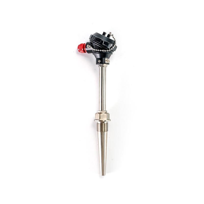
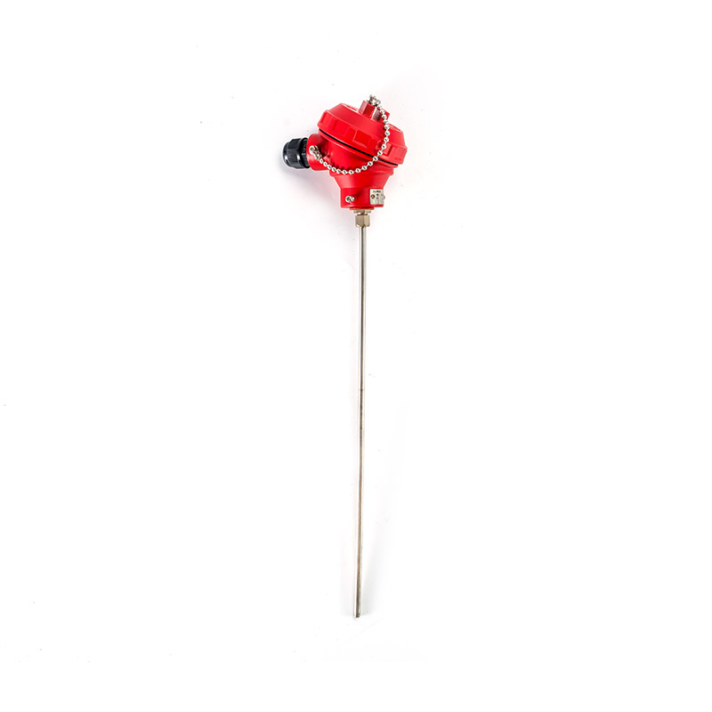
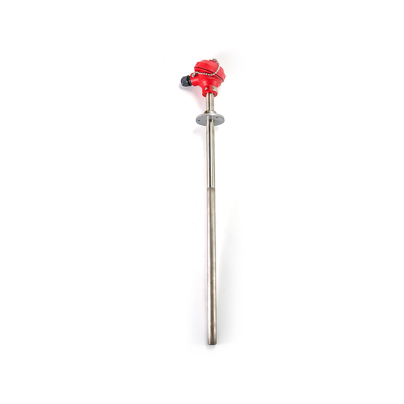
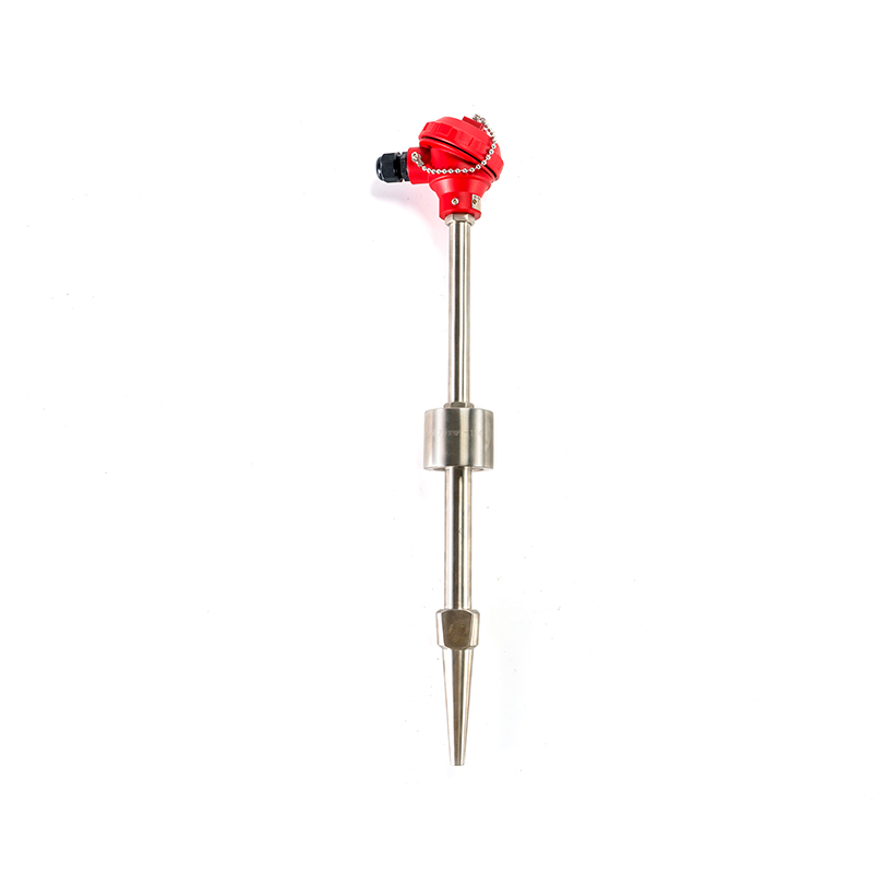
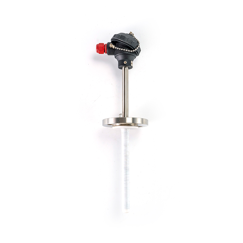
The classic assembly places a thin film element in a stainless steel or Inconel protection tube, seals it with a connection head, and terminates the leads on a ceramic terminal block. A head-mounted transmitter turns the resistance into a 4 to 20 mA signal at the point of measurement, which removes long lead runs from the accuracy budget and lets a standard instrument cable carry the signal back to the control room. This is the workhorse configuration for tanks, pipelines, dryers and heat exchangers.
Where a rigid probe will not fit or where the sensor must follow a curved path, a sheathed construction with a mineral-insulated cable and a bendable section works well. The magnesium oxide insulation compacts the element and leads, gives good thermal contact, and provides electrical isolation. These probes are common on plastic extruders, small pipework and machinery where access is difficult.
Explosion-proof heads, intrinsically safe transmitters and multi-point probes with several elements at different depths all exist for good reasons. A multi-point assembly, for instance, lets one penetration through a vessel wall report the temperature at three levels, which is often cheaper and simpler than three separate nozzles. Choose these options when the hazard assessment, the vessel geometry or the maintenance plan demands them, not simply because they look more robust on a catalogue page.
Three questions settle most assembly choices. How deep can the probe be inserted, and is that depth at least ten times the sheath diameter plus the length of the sensing element? What is the process pressure and flow velocity, and will the sheath vibrate? And what happens electrically if moisture reaches the terminal block? If you cannot answer those three, the assembly that arrives will be a compromise.
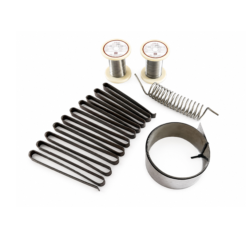
Not every part of a temperature system is a temperature sensor. Lead wires, extension cables and compensating conductors decide how cleanly the signal travels, and the same plant often needs resistance alloys and thermocouple alloy wire for other measurement and heating duties.
Inside a probe, lead wire material matters. Nickel and nickel-plated copper conductors are common because they resist oxidation at moderate temperatures and weld reliably to the element. Silver-plated copper offers lower resistance but degrades faster if moisture enters the assembly. Where the internal wiring must survive higher temperatures, nickel or nickel-based alloys are used instead, at the cost of slightly higher resistance and a stiffer feel.
Outside the probe, extension and compensating conductors connect the sensor to the instrument. For a resistance element the requirement is simple: matched, low-resistance copper cores with consistent cross-section and good shielding. For thermocouple circuits the requirement is different, because the extension wire must match the thermoelectric characteristics of the couple, and the wrong alloy introduces an error at every connection point. Plants often run both systems side by side, which is why buying conductors from a supplier who understands both is worth the small price difference.
Alloy quality also shows up in the wire used for resistance and heating duties. Consistency of resistivity, diameter tolerance and surface finish all affect how a wire performs after it is wound or formed. A guide to the main alloy wire types, their structure and how to select them is available for readers who specify these materials alongside their temperature sensors.
Price differences between suppliers of what looks like the same probe are usually explained by what is not shown on the quotation: element source, trimming tolerance, cable grade, calibration data and terminal hardware. A structured comparison takes twenty minutes and saves months.
Start with traceability. Ask whether the element comes with a batch number and whether the finished probe is tested individually or by sampling. A supplier who tests every unit and keeps the records can answer a quality complaint with data. A supplier who tests by sampling cannot.
Then look at the calibration offer. A serious manufacturer can provide a certificate with measured values at the ice point and at a second temperature, together with the uncertainty of the reference used. Two points are enough for most industrial work; three points suit narrow-span or regulated applications.
| What to verify | Question to ask | A solid answer looks like |
|---|---|---|
| Element traceability | Can you identify the element batch in the finished probe? | Batch number marked on the probe or the certificate |
| Tolerance verification | Is each unit measured at 0 °C, or only sampled? | Individual measurement with recorded values |
| Calibration certificate | Which temperatures and what reference uncertainty? | Ice point plus a second point, stated uncertainty |
| Drawing control | Will you manufacture to my drawing, revision controlled? | Approved drawing with revision number |
| Sheath and cable grade | Which stainless grade, which insulation, which cable? | Named grades, not just "stainless" |
| Terminal and head | Can the head accept a transmitter later? | Standard fitting, compatible terminal spacing |
| Batch consistency | How much variation between shipments? | Defined acceptance window and records |
| After-sales support | Who investigates a drift complaint? | A named engineer and a return process |
Two commercial points deserve equal attention. First, ask how the supplier handles small development orders. A manufacturer who can deliver a handful of prototypes in a specific length, and then scale to production, is more useful than one who only quotes container volumes. Second, confirm what happens if the tolerance is missed. A written commitment to replace out-of-tolerance units is a reasonable request, and the answer tells you a lot about how the factory is run.
When comparing quotations, convert everything to the same basis. A probe quoted without a transmitter, without calibration data and with a shorter sheath is not cheaper; it simply moves the cost to your commissioning team.
An installation error costs more accuracy than a grade upgrade. Work through the mechanical points first, then the electrical ones, then the verification.
Immersion is the most common problem. As a rule, the inserted length should be at least ten times the sheath diameter, plus enough to cover the sensing element, so the stem does not conduct heat away from the tip. In small pipework, angle the probe into the flow rather than fitting it perpendicular, and place it where the fluid is moving rather than in a dead leg. Use a thermowell with proper contact and, where the process allows it, a small amount of thermal compound to improve coupling.
Check the process connection torque and the orientation of the head so that moisture cannot run into the terminal block. Cable glands facing upward are a slow leak waiting to happen.
Keep sensor cables away from variable frequency drives and motor cables, and where a crossing is unavoidable, cross at right angles. Shield the cable and earth the shield at the instrument end only. Verify the insulation resistance of a mineral-insulated probe before connection; a reading well above one hundred megohms at one hundred volts DC is a reasonable expectation for a dry, undamaged probe.
Confirm the wiring count matches the instrument input. Then confirm the transmitter range covers the process window with margin. A transmitter configured for 0 to 100 °C will clip during a clean-in-place cycle, and the resulting data gap is often discovered weeks later.
A simple ice-point check at the terminal head, or a comparison against a second probe within a few centimetres, catches most problems before production starts. Record the as-found reading, the ambient temperature and the wiring configuration. If the same probe is later suspected of drifting, that record is what turns an argument into a decision.
There are applications where a thin film element will disappoint, and recognising them early is part of specifying well.
Sustained temperatures above roughly 500 °C are the clearest case. Furnaces, kilns, exhaust ducts and some heat treatment processes fall into this group, and a wire-wound element or a thermocouple is usually the better answer. Very rapid thermal cycling is a second case: repeated excursions over a wide range accelerate the stress that drives drift, even if the peak temperature looks acceptable on paper.
Mechanical abuse is a third. Thin film elements are small and stiff, but the substrates are brittle. A probe that is regularly struck by falling material, or inserted into a stream carrying coarse particles, will fail at the sheath long before the element is at fault. The correct response is a heavier sheath or a hard facing, not a different element.
Where the medium is abrasive, a coated or armoured probe protects the element and keeps the measurement stable. In slurry lines, crystallising chemicals and pneumatic conveying ducts, the wear occurs on the outside of the probe, and once the sheath is penetrated the element follows quickly.
Moisture ingress is the fourth case. If a probe is washed down daily or sits in a condensing atmosphere, the assembly needs a sealed head, proper glands and a cable that tolerates the environment. A premium element behind a leaking gland will read badly within weeks.
Finally, hydrogen and some reducing atmospheres at high temperature can affect platinum elements. If your process includes these conditions, raise the question with the manufacturer before ordering rather than after the first failure.
Most purchasing problems with temperature sensors are not technical mysteries. They are familiar commercial shortcuts with predictable consequences.
The pattern is the same in each case: the saving is visible on the invoice, the cost appears in maintenance hours, product quality deviations and repeated root-cause investigations. A wholesaler or trading company can be a perfectly good source if it controls these variables; the difficulty is not the business model, it is the absence of documentation.
A thin film RTD is a platinum resistance element in which a very thin platinum layer is deposited on a ceramic substrate and patterned into a resistive track. The element is trimmed so that its resistance equals a defined value, such as 100 or 1000 ohms, at 0 °C. As temperature rises, resistance rises in a predictable way, and the connected instrument converts that change into a temperature reading. The construction is fast responding and compact, which is why it dominates general industrial measurement.
At moderate temperatures the two can meet the same tolerance class, so accuracy is comparable when both are measured and certified. The difference appears over time and at temperature. Wire-wound elements generally hold their value better above 500 °C and under repeated wide-range cycling, while thin film elements offer faster response and better vibration tolerance in the range where most plants actually operate.
Choose Pt100 when you need low excitation current, four-wire measurement or a wide choice of transmitters. Choose Pt1000 when the cable run is long and you want a two-wire loop without significant lead-resistance error, or when several sensors share a compact instrument. For a Pt1000 element, keep the excitation current low so self-heating stays small.
It can survive short excursions, but continuous service above roughly 400 to 500 °C accelerates drift in most thin film constructions. If your process sits in that region permanently, a wire-wound element or a thermocouple is usually the more economical long-term choice once you count replacement labour and lost production.
Service life depends far more on temperature, cycling and moisture than on the element alone. A probe in a stable 150 °C water circuit may last many years, while the same element in a cycling 450 °C process may drift out of tolerance in months. Track as-found readings at each maintenance interval so the plant learns its own replacement interval instead of guessing.
Use four-wire when you need the best accuracy, when the cable run is long and its resistance is uncertain, or when the measuring span is narrow. Three-wire is adequate for most industrial loops and is what most head-mounted transmitters accept. Whichever you choose, keep the cores matched and avoid mixing cable from different batches on the same loop.
Use a thermowell when the process is pressurised, corrosive, or must keep running while the sensor is replaced. A thermowell also protects the probe from flow-induced vibration and mechanical damage, at the cost of a slower response. For clean, low-pressure services where maintenance can be planned, a direct-immersion probe is sometimes the better compromise.
Send the process medium, the operating and peak temperatures, the pressure, the required immersion length and connection size, the element type and class, the wiring configuration, the head or transmitter requirement, and the quantity including spares. If you can add the calibration temperatures you need, the quotation will come back complete instead of raising five follow-up questions.
The practical sequence is straightforward: identify the process window, choose the element type and class for that window, choose a wiring configuration that matches the instrument, then select an assembly that survives the environment. Everything else, including brand preference, follows from those four decisions.
Temperature instrument range: browse assemblies built around platinum resistance elements, from head-mounted probes to sheathed and hazardous-area versions.
View the full temperature instrument range
Reference reading: if you also specify conductors and alloy wire, the selection guide covers the main types, their structure and how to match them to an application.
Both pages are worth a look before you finalise a specification, because they cover the parts of the measurement chain that sit outside the element and are most often left undefined on a purchase order.
Thin film RTD technology has earned its place because it solved a set of practical problems at once: small size, fast response, good vibration behaviour and economical volume production. None of those advantages compensate for a wiring error, a shallow immersion depth or a sheath that cannot survive the process. The buyers who get the best long-term results are the ones who treat the element, the circuit and the assembly as a single specification, and who ask their manufacturer for measured data rather than a class letter.
When you are ready to move from specification to procurement, a clear enquiry with process conditions, quantities and calibration requirements will get you to a workable answer quickly, and a supplier who responds with drawings and test data is usually the one worth keeping.



 INQUIRY
 English
 عربى
عربى русский
 中文简体
中文简体