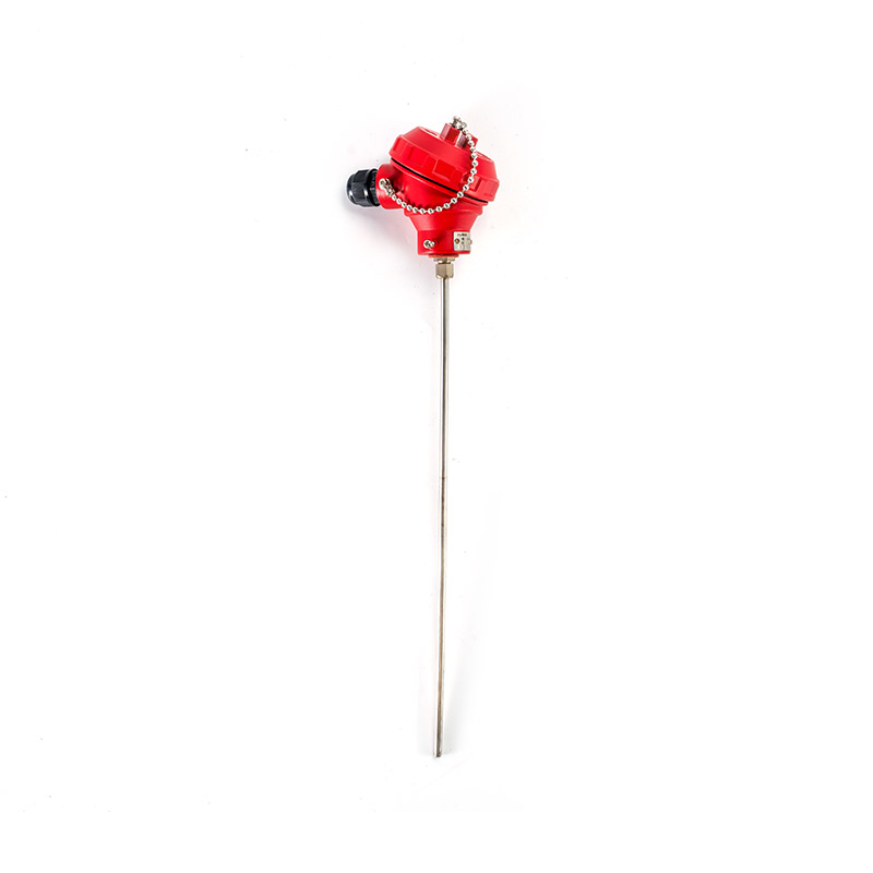
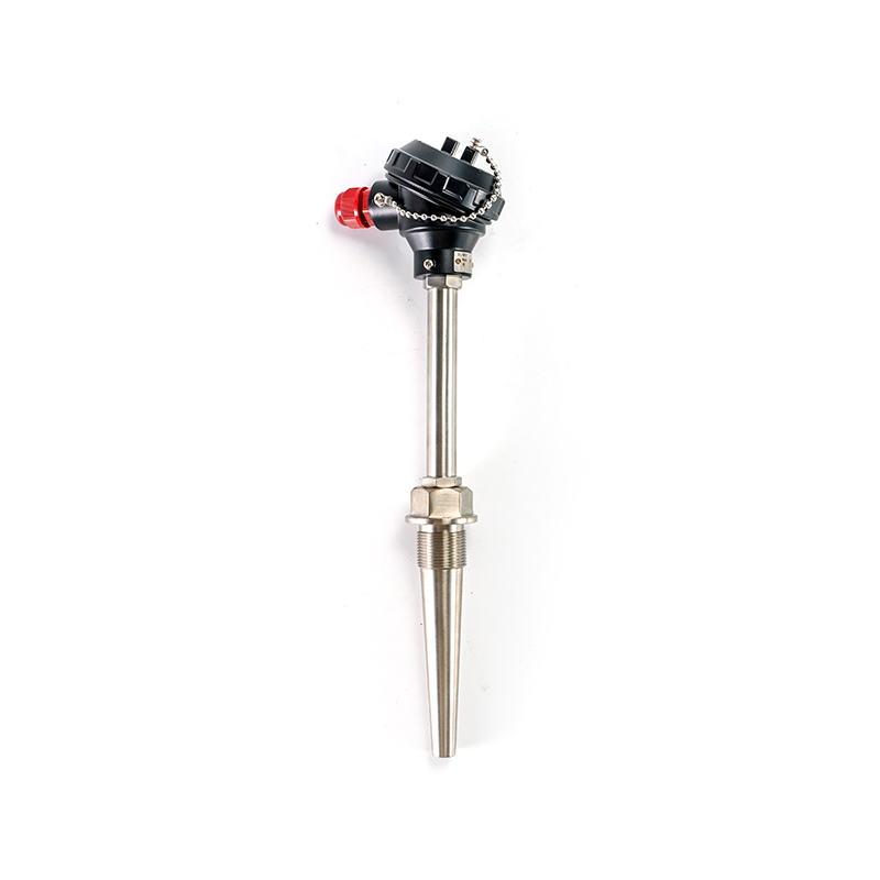
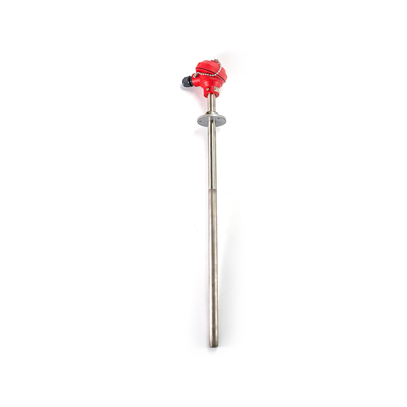
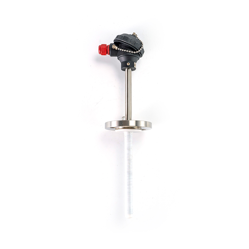
1. Definition:
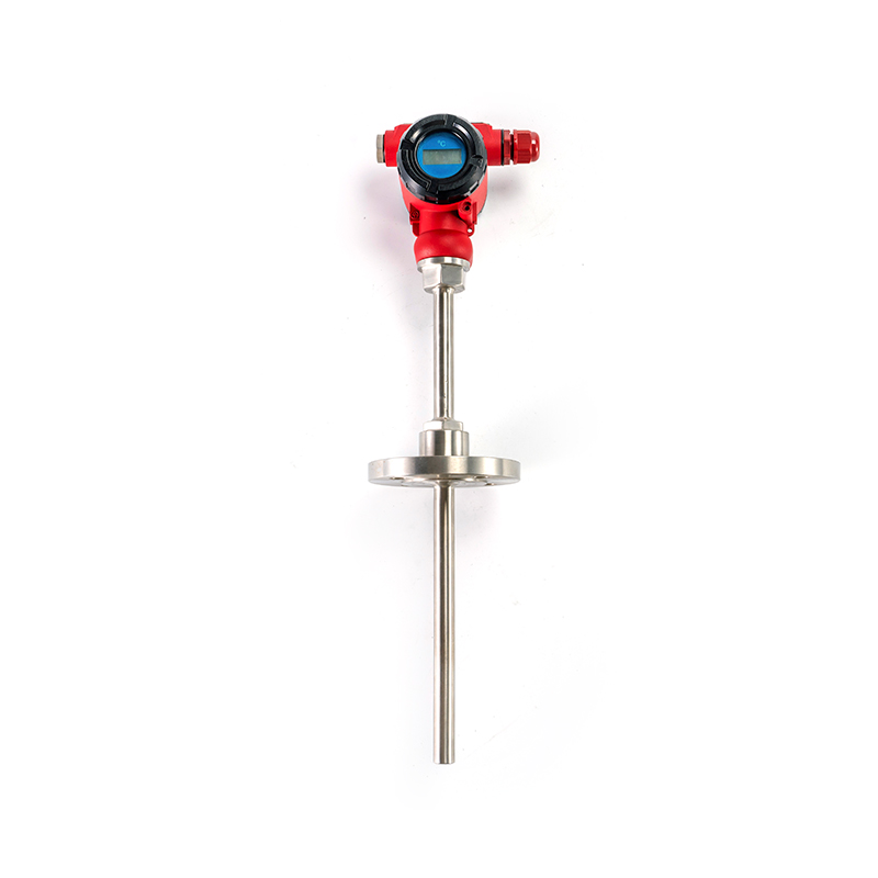
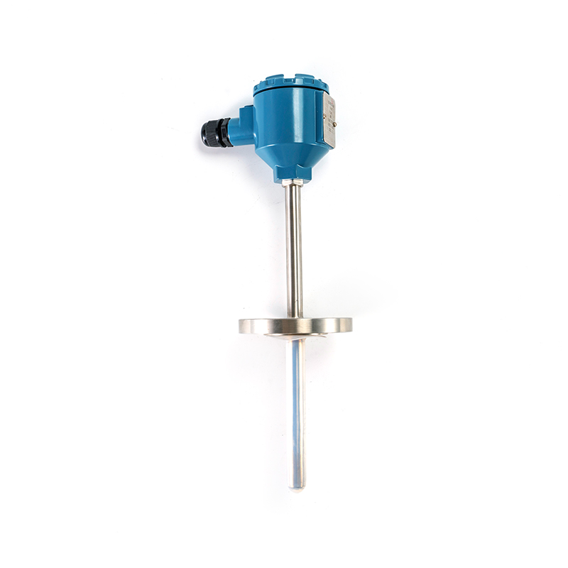
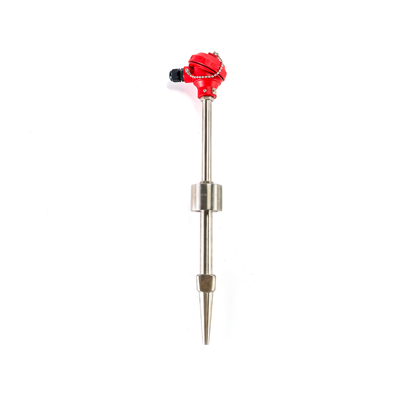
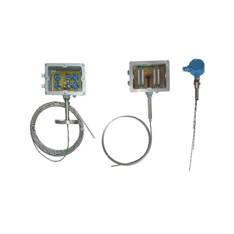
Temperature instruments are industrial automation devices used for detecting, displaying, controlling, and recording temperature parameters. They primarily employ sensing elements such as thermocouples, thermistors, and infrared sensors to convert temperature signals into electrical or digital signals, enabling measurement, transmission, regulation, alarm functions, and remote communication. These instruments serve as essential foundational detection and control equipment in industrial production, equipment operation, and environmental monitoring.
2. Main Features:
3. Applicable Industries:
Metallurgy and Steel: Temperature monitoring for blast furnaces, converters, heating furnaces, annealing furnaces, smelting, and heat treatment processes.
Mechanical Manufacturing: Casting, forging, welding, quenching, temperature rise of bearings and motors, and temperature measurement of air compressor systems.
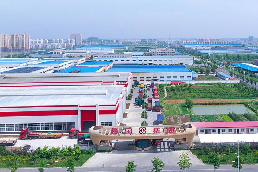
Founded in
Cover an area of
Experienced employees
Building area

A heat-treatment line that replaced its protection tubes every six weeks did not have a thermocouple problem. It had a ceramic problem. The elements came out of service clean and unbroken, yet the tubes had cracked, spalled or bowed, and the drift that followed belonged to the t...

The first sign that something is wrong with a thin film RTD is rarely a dramatic failure. It is a slow disagreement with a neighbouring sensor, a reading that creeps during a heat-up cycle, or a batch trend that no longer matches the recipe. In one case, a food processor replace...
A dairy processor in eastern China spent three weeks chasing a pasteurizer fault that turned out to be one crossed thermocouple extension wire inside a junction box. The recorder kept writing believable numbers the whole time, which is precisely why the investigation took so lon...
A heat-treat line running at 900 degrees Celsius will usually consume a Type K thermocouple in eight to fourteen months. The same probe sitting in a clean water loop at 90 degrees Celsius often survives eight years or more. Nothing about the two probes looks different on a datas...
This category covers the sensors, transmitters and displays used to measure process temperature across industrial, laboratory and educational settings. Temperature instruments in this group include contact sensors such as thermocouples and resistance temperature detectors, non-contact infrared devices, mechanical bimetallic gauges, and the transmitters and digital display units that turn a sensor's signal into a number you can read or send elsewhere. Every device here does the same basic job, turning a temperature condition into an electrical or mechanical reading, but each is built differently and suited to a different set of process conditions.
Choosing between these instruments usually comes down to matching the device to the operating temperature range, the physical environment, and how accurate or fast-responding the control loop needs to be. The sections below walk through common types, key features, typical industries, how each device works, selection guidance, performance comparisons, and maintenance tips for this category, along with answers to frequently asked questions.
This category covers the sensing, transmission, and display equipment used to monitor process temperature across a wide range of industrial applications.
Five device types make up most of the equipment found in this category. Each is built around a different physical measuring principle, which is why response speed, mechanical durability, and typical placement vary so much from one type to the next.
(1) ThermocouplesTwo different metal wires joined at a tip create a small voltage that changes with temperature, an effect known as the Seebeck effect. The wire pair usually sits inside a sealed metal sheath packed with mineral insulation for protection. Thermocouples are a common choice for furnace, boiler and reactor monitoring, where a wide temperature range and resistance to mechanical stress both matter. |
(2) Resistance Temperature Detectors (RTDs)A metal element, usually platinum, changes its electrical resistance in a predictable way as temperature changes, and a measurement circuit turns that resistance change into a temperature reading. RTDs are chosen where the reading needs to stay steady over a long service life, such as pipeline and vessel monitoring in chemical and food processing lines. |
(3) Bimetallic Temperature InstrumentsTwo metal strips that expand at different rates are bonded together, so a change in temperature bends the strip and moves a pointer across a dial. These instruments give a simple, local reading at a process point without needing external power or an electronic display. |
(4) Infrared (Non-Contact) Temperature InstrumentsThese devices pick up the infrared radiation a surface naturally gives off and convert it into a temperature reading without ever touching the target. Infrared instruments are used where touching the surface isn't practical, such as moving equipment, molten material, or a surface that shouldn't be disturbed by a probe. |
(5) Temperature Transmitters and Digital Display InstrumentsA transmitter takes the raw signal from a thermocouple or RTD and converts it into a standardized output that a control system can use, while a digital display instrument shows the reading locally as a number. Together, these bring field sensor data into a centralized monitoring or automation system, or simply give an operator a readable number right at the measurement point. |
Because each of these five types relies on a different physical principle, they usually can't just be swapped for one another at the same measurement point. A control loop built around a thermocouple input, for example, generally can't be switched to an RTD without also changing the transmitter or input card that goes with it.
Thermocouples, resistance temperature detectors, bimetallic instruments, infrared instruments, and transmitters each measure temperature through a different physical principle, which shapes where each type is typically installed.
Beyond the specific sensing principle a device uses, buyers looking at temperature instruments generally check a shared set of performance and construction traits that determine how well an instrument will hold up on an actual production line. These traits span measurement coverage, accuracy class, mechanical durability, resistance to a harsh environment, signal compatibility with existing control systems, and any extra functions built into the instrument beyond a basic reading. Looking at these factors together, rather than any single spec on its own, gives a clearer picture of how an instrument will perform once it's installed. The list below covers the main features most often compared across temperature instruments in this category.
Taken together, these features explain why temperature instruments are treated as a configurable platform, where sensing element, accuracy class, signal output, and installation method are matched jointly to a specific measurement point.
Because sensing element, accuracy class, and signal output within this category can be combined in many ways, temperature instruments end up specified across a broad range of industries rather than one narrow application. What these sectors share is a need for dependable temperature indication, control, or logging at a specific point in a process line, furnace, or piece of rotating equipment, often under vibration, corrosive exposure, or tight process tolerances. The table below lists several representative sectors along with typical monitoring points where thermocouples, RTDs, bimetallic instruments, infrared instruments, or transmitters are commonly installed.
| Industry Sector | Typical Monitoring Points |
|---|---|
| Petrochemical | Reactors, distillation towers, pipelines, storage tanks, and refining units |
| Electric Power and Energy | Boilers, steam turbines, generators, heat exchangers, transformers, cables, and new energy equipment |
| Metallurgy and Steel | Blast furnaces, converters, heating furnaces, annealing furnaces, smelting, and heat treatment processes |
| Mechanical Manufacturing | Casting, forging, welding, quenching, bearing and motor temperature rise, and air compressor systems |
| Building Materials | Cement kilns, glass melting furnaces, ceramic kilns, and brick, tile, and refractory production |
| Food and Pharmaceutical | Sterilization, fermentation, roasting, cold chain warehousing, pharmaceutical reactors, and cleanroom monitoring |
Xinguo Group Co., Ltd. develops and supplies temperature, pressure, level, and flow instrumentation that supports several of these sectors, reflecting a broader engineering approach in which temperature instruments are considered alongside related process instrumentation rather than as an isolated component.
The table below matches common application environments with the instrument type most often chosen for that environment. Treat this as a general starting point rather than a fixed rule, since a real process can involve more than one of these factors at once.
| Application Environment | Commonly Selected Instrument |
|---|---|
| High-temperature furnace or kiln monitoring | Thermocouple, sheathed construction |
| Long-term stable monitoring in a clean pipeline | Resistance Temperature Detector (RTD) |
| Local, power-free point reading | Bimetallic Temperature Instrument |
| Moving, hazardous, or inaccessible surface | Infrared Temperature Instrument |
| Integration with an automated control system | Temperature Transmitter with digital display |
Matching operating range, response speed, contact requirement, and mechanical environment to the instrument construction is more reliable than selecting by industry label alone.
Response time is how quickly an instrument's reading catches up to an actual change in process temperature, and it varies quite a bit across the four core sensing technologies covered in this category. This difference mainly comes from the physical mass and construction around the sensing element, not from the electronics attached to it. A thin-sheathed thermocouple or a non-contact infrared device generally reacts faster than a bulkier resistance element or a mechanical dial movement. The chart below shows typical response time in seconds for a thermocouple, an RTD, a bimetallic instrument, and an infrared instrument, based on general engineering reference figures for each construction type. It's worth reviewing this comparison before specifying an instrument for a fast-cycling process, where lag directly affects control accuracy.
The chart shows the infrared instrument responding fastest of the four, which fits its non-contact measuring principle, since there's no physical mass to heat or cool before the reading changes. The thermocouple comes next, helped by a thin metal sheath and a small internal thermal mass around the measuring junction. The RTD responds noticeably slower than the thermocouple in this comparison, largely because the resistance element and its protective sheath usually carry more thermal mass, and self-heating limits in the measurement circuit also cap how quickly the reading can update. The bimetallic instrument is the slowest of the four, which fits its mechanical design, since the bonded metal strip has to physically expand and move a pointer mechanism rather than simply changing an electrical signal. That doesn't make the bimetallic instrument a poor choice in general, since many local indication points don't need a fast response and instead benefit more from a simple, self-contained design that needs no external power. A process with rapid temperature swings, such as an extrusion line or a fast batch reaction, generally benefits from the quicker response of a thermocouple or an infrared instrument paired with a well-tuned control loop. A process with slow, steady thermal behavior, such as a large storage tank, can usually accept the slower response of an RTD or a bimetallic gauge without any real effect on control performance. Response time also depends on the surrounding medium, since a sensor in flowing liquid typically responds faster than the same sensor sitting in still air. Because these figures are general reference values rather than measured data for a specific product, engineers working on time-critical control loops should confirm the actual response characteristics with their instrument supplier for the exact construction being specified. In practice, many plants use more than one instrument type across a single process area, putting faster sensors at control-critical points and slower, simpler instruments where local indication is all that's needed.
Non-contact infrared and thin-sheathed thermocouple designs generally respond faster than RTD and bimetallic constructions, which carry more thermal or mechanical mass around the sensing element.
Calibration stability is how closely an instrument's reading keeps matching true process temperature after months of continuous service, and it's a separate trait from response speed or day-one accuracy. Some constructions hold their original calibration more closely over time than others, largely because each sensing element ages differently under repeated thermal cycling. This matters for maintenance planning, since a device that drifts faster generally needs more frequent checking against a reference point. The line chart below plots an illustrative drift trend, in relative percentage terms, across twelve months of continuous operation for the same four instrument types discussed above. Seeing this general pattern helps a maintenance team plan verification intervals rather than applying the same schedule to every instrument type.
The RTD line stays closest to the horizontal axis across the full twelve months, which reflects the generally strong long-term stability of a platinum resistance element, since its resistance-temperature relationship tends to stay consistent across repeated thermal cycles. The thermocouple line shows a moderate, fairly steady upward drift, a recognized trait of base-metal thermocouple wire, since the alloy at the measuring junction can shift gradually with prolonged high-temperature exposure. The infrared line sits between the RTD and thermocouple lines for most of the period, showing fairly modest drift that's more often linked to gradual changes in the optical path, such as lens contamination, than to the electronic detection components themselves. The bimetallic line shows the steepest upward trend of the four, which fits its mechanical build, since repeated expansion and contraction of the bonded metal strip can gradually affect spring tension and pointer alignment over time. None of these four lines shows a sudden jump, which is expected, since calibration drift in continuously operating instruments is typically a gradual process rather than a sudden failure. This general pattern suggests that RTD-based measurement points can often go longer between verification checks than bimetallic gauges, though every plant should base its own verification schedule on its actual process tolerance rather than on a general chart. For infrared instruments, keeping the lens or optical window clean has a direct effect on how closely the drift trend shown here is followed in practice. For thermocouples used in high-temperature furnace zones, drift can accelerate beyond what's shown here if the instrument runs continuously near the top of its rated range. Because this chart shows illustrative relative values rather than measured data for a specific product line, treat it as a general planning reference rather than a guaranteed drift curve for any individual instrument. Maintenance teams typically combine this kind of general pattern with periodic cross-checks against a secondary reference point to catch drift before it affects product quality or process control.
RTDs generally show the strongest long-term calibration stability among the four instrument types, while mechanical bimetallic instruments tend to drift more over extended continuous service.
Accuracy tolerance is how far a reading can typically stray from true temperature under normal operating conditions, and it's commonly given as a percentage figure in general industry reference material. A smaller tolerance means a tighter, more precise reading, while a larger one means a wider acceptable margin. This is a separate trait from response speed and calibration drift, though all three are often weighed together when specifying an instrument for a demanding measurement point. The column chart below compares typical accuracy tolerance, as a percentage of reading, across the same four instrument types covered earlier. This comparison is meant as general reference information rather than a certified specification for any individual product.
The RTD column is the shortest of the four, reflecting the tight tolerance commonly associated with a well-matched platinum resistance element and measurement circuit. The thermocouple column is noticeably taller, consistent with the wider tolerance typically seen with base-metal thermocouple wire compared with a resistance element, though this wider tolerance is generally accepted in exchange for the thermocouple's broader temperature range and mechanical durability. The infrared column sits close to the thermocouple column, since non-contact accuracy depends heavily on correctly matching the emissivity setting to the target surface, and a mismatch there is a common source of extra reading error beyond the instrument's base tolerance. The bimetallic column is the tallest in the chart, reflecting the comparatively wider tolerance typical of a mechanical dial movement compared with an electronic sensing element. A wider tolerance doesn't automatically make an instrument unsuitable, since many local indication and general monitoring points don't need the tighter tolerance an RTD offers. Picking an instrument on tolerance alone, without also weighing response speed and mechanical durability, can lead to a mismatch between the sensor and what the process actually needs. For measurement points feeding a tightly controlled process, such as a chemical reaction with narrow temperature limits, the tighter tolerance of an RTD is often weighed against its slower response time from Section 6. For general indication points, such as a storage tank or a utility line, the wider tolerance of a thermocouple or bimetallic instrument is often acceptable given the broader range or simpler installation each offers. Because accuracy tolerance figures vary by specific product design and manufacturing process, it's worth confirming the exact tolerance class with an instrument supplier whenever a measurement point has a defined accuracy requirement. Combining this tolerance comparison with the response time and calibration stability data from the previous two sections gives a fuller picture than any single chart on its own.
RTDs typically offer the tightest accuracy tolerance among the four instrument types, while thermocouples, infrared instruments, and bimetallic gauges each accept a wider tolerance in exchange for a broader range or simpler installation.
The table below summarizes the four core instrument types across four practical specifications covered earlier, giving a compact reference for comparing quotations or planning a measurement point.
| Specification | Thermocouple | RTD | Bimetallic | Infrared |
|---|---|---|---|---|
| Contact Requirement | Contact | Contact | Contact | Non-Contact |
| Typical Temperature Range | Widest | Moderate | Narrower | Moderate |
| Common Output Signal | Millivolt signal | Resistance signal | Mechanical dial | Electronic signal |
| Typical Installation | Thermowell or direct weld | Thermowell | Threaded stem | Fixed or handheld mount |
The radar chart below brings together five dimensions in one view: temperature range, response speed, long-term stability, mechanical durability, and maintenance simplicity, each scored on a relative one-to-five scale. This kind of shape-based comparison is useful precisely because no single instrument type scores highest on every dimension at once. Reading the overall outline of each shape generally tells you more about a device's practical fit than looking at any single axis alone. A design that scores well on temperature range, for example, commonly gives up some ground on response speed or maintenance simplicity, and that pattern repeats across engineered instruments of many kinds. The chart is meant to support the selection process from Section 5, not replace it.
The thermocouple shape extends furthest along the temperature range axis, which lines up with its common use in high-temperature furnace and kiln monitoring from Section 2. The RTD shape reaches furthest along the long-term stability axis, matching the calibration drift pattern from Section 7, though it pulls back noticeably on response speed for the reasons explained in Section 6. The bimetallic shape is clearly strongest on mechanical durability and maintenance simplicity, since a self-contained mechanical movement has no electronic components to fail and generally tolerates a harsher physical environment than an electronic sensor. The infrared shape stands out on the response speed axis, consistent with its non-contact principle, while staying more moderate on temperature range and long-term stability compared with the thermocouple and RTD. None of the four shapes leads on every axis at once, which is an expected outcome rather than a shortcoming unique to any one design, since improving one property, such as adding a heavier mechanical movement for durability, generally costs something on another property, such as response speed. Looking at all four shapes together makes it easier to see that the four instrument types complement each other rather than compete head-to-head across the same applications. A plant with several different measurement points often ends up using more than one instrument type across the facility, putting each type where its particular strength matches the specific requirement at that point. For a buyer working with a manufacturer or supplier, this radar comparison can serve as a starting reference before moving into the more detailed selection factors described in Section 5. Because the scoring here is illustrative rather than measured laboratory data, teams with strict performance requirements should ask for specific technical data on the exact product configuration being considered. Read together with Table 2 above, this chart is meant to support a more informed conversation with an instrument supplier rather than serve as a final specification on its own.
Each of the four core instrument types is strongest along a different practical dimension, so matching the overall shape to the actual process priority is more useful than searching for a single instrument that leads on every axis.
A small set of consistent practices supports reliable long-term performance across all four instrument types described in this article. The steps below follow a general order that many maintenance teams use during routine walkdowns and scheduled service windows.
1
Confirm correct installation depth and orientation for each sensor before the process is brought back online. 2
Inspect the sheath or housing surface periodically for wear, corrosion, or physical damage. 3
Check electrical connections and insulation resistance on contact-type sensors at scheduled intervals. 4
Clean the lens or optical path on infrared instruments to limit reading drift from surface contamination. 5
Verify dial movement and pointer response on bimetallic instruments during routine walkdowns. 6
Cross-check sensor readings against a reference measurement point during planned maintenance windows.
Following these steps consistently, rather than only when a reading looks off, helps a plant catch a slowly developing issue, such as gradual sheath wear or lens contamination, before it affects product quality or process control. Keeping a maintenance log for each measurement point also makes it easier to spot a recurring pattern, such as a sensor location that consistently drifts faster than others in the same process area.
Consistent inspection of installation depth, sheath condition, electrical connections, and reference cross-checks supports reliable long-term performance across all four instrument types.
When comparing manufacturers or suppliers for temperature instruments, buyers generally check whether a company produces its own sensing elements and alloy wire in-house or assembles instruments from externally sourced components. A supplier with in-house wire and alloy production is typically better positioned to keep calibration characteristics consistent across a larger order, since the base material is controlled from the earliest stage of production rather than bought in from an unrelated third party.
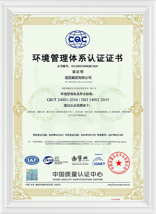
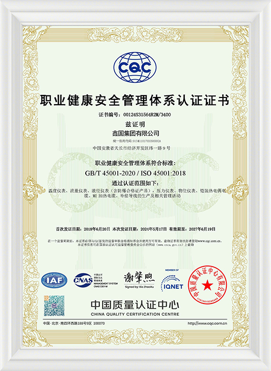
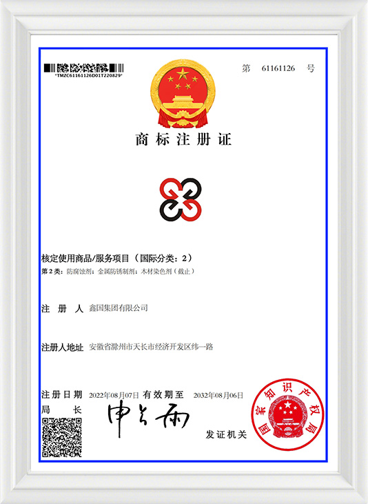
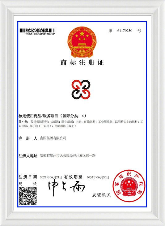
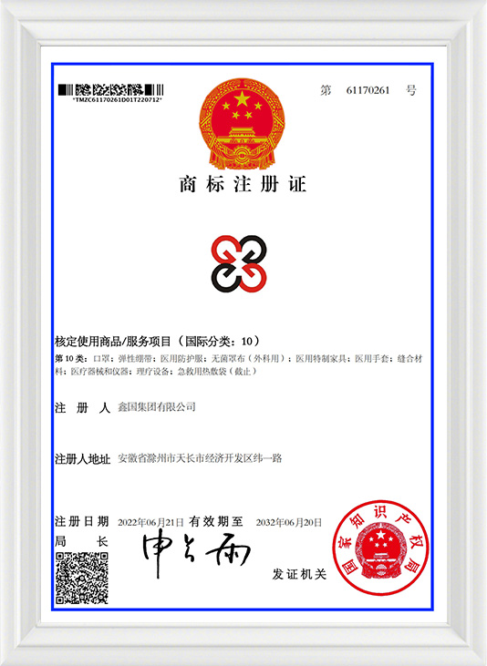
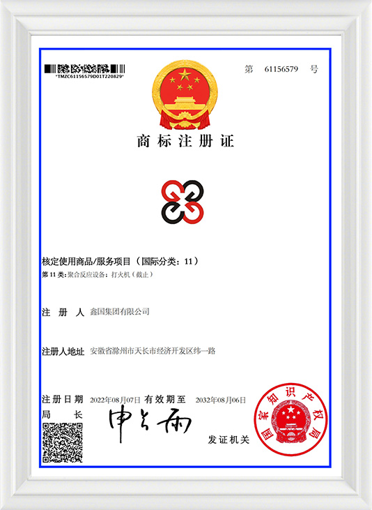
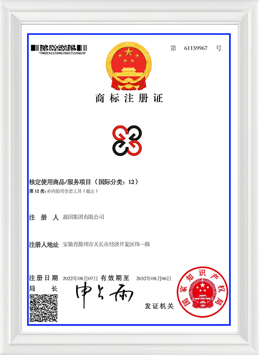
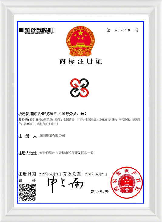
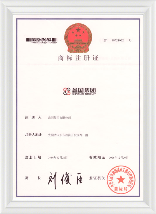
Xinguo Group Co., Ltd. is built around this kind of integrated model. Founded in 1997 and based in Tianchang City, Anhui Province, the company has grown to employ more than 300 people, including over 50 professional and technical staff such as senior engineers, engineers, and assistant engineers. Its product range covers temperature, pressure, level, and flow instruments alongside digital display equipment, various power and control cables, mineral-insulated heating cables, distribution and automation control systems, instrument valves, and laboratory equipment, applied across power, petroleum, chemical, metallurgy, building materials, machinery, food, aerospace, and new energy sectors.
As part of this integrated approach, Xinguo Group Co., Ltd. also produces precision alloy materials specifically for thermocouple manufacturing, with a product range covering thermocouple alloy wire in K, N, E, J, and T types, compensation alloy wire types such as KX, EX, NX, JX, TX, KCA, KCB, NC, and SC, high-resistance heating alloys, precision resistance alloys, pure nickel wire, manganese-copper alloys, and Monel alloys used across aviation, petroleum, chemical engineering, machinery manufacturing, and power and energy industries.
For a buyer sourcing thermocouples, RTDs, bimetallic instruments, infrared instruments, or transmitters as a wholesale supplier, an exporter, or an OEM or ODM partner, this kind of upstream wire and alloy capability is a practical sign of consistent production quality across an order, particularly for measurement points where matched calibration across many sensors matters.
A manufacturer with in-house wire and alloy production capability is generally better positioned to support consistent temperature instrument orders at scale.
The questions below cover common points that come up when comparing temperature instruments across the four core sensing technologies described in this article.
Q1: What is the main difference between a thermocouple and an RTD?A thermocouple generates a small voltage from two dissimilar metal wires joined at a junction, while an RTD measures a predictable change in electrical resistance in a metal element. RTDs typically offer tighter accuracy and better long-term stability, while thermocouples generally cover a wider temperature range and respond faster. |
Q2: When is a non-contact infrared instrument preferred over a contact sensor?An infrared instrument is generally preferred when direct contact with the target surface is impractical, such as on moving equipment, molten material, or a surface that should not be disturbed by a probe. Correct emissivity setting for the target material has a direct effect on measurement accuracy. |
Q3: Do bimetallic temperature instruments require electrical power to operate?No, a bimetallic instrument operates through mechanical deflection of a bonded metal strip and does not require an external power source, which is one reason it remains common for local, direct-reading indication points. |
Q4: What role does a temperature transmitter play in a measurement system?A temperature transmitter conditions and converts a raw signal from a thermocouple or RTD into a standardized output signal, allowing the reading to be transmitted reliably to a control system or displayed digitally at a distance from the sensor. |
Q5: Can a manufacturer customize temperature instruments for a specific process?Yes, a manufacturer with in-house sensor and alloy production capability can typically customize sheath material, insertion length, junction style, and output signal to match a specific process, supporting both wholesale orders and OEM or ODM configurations. |
Q6: What signal outputs are commonly available for integration with a PLC or DCS system?Common standardized outputs include 4 to 20mA, RS485, HART, digital signals, and relay contacts, allowing temperature instruments to be integrated directly into existing automation and control infrastructure. |



 INQUIRY
 English
 عربى
عربى русский
 中文简体
中文简体