A dairy processor in eastern China spent three weeks chasing a pasteurizer fault that turned out to be one crossed thermocouple extension wire inside a junction box. The recorder kept writing believable numbers the whole time, which is precisely why the investigation took so long. The short answer is that a multi channel thermocouple data logger is only as trustworthy as the four things around it: the sensor, the compensating cable, the cold junction reference, and the engineer who wrote the channel map.
If you are specifying a logger for furnace surveys, pilot reactors, retort validation, battery thermal testing, or cold chain work, the decisions that actually matter are channel count, input isolation, cold junction accuracy, scan interval, and memory depth. Everything else, including screen size, enclosure colour and phone app design, is secondary.
This guide covers what the instrument does, how the measurement chain behaves from junction to logged value, the specifications worth arguing about, the wiring habits that quietly ruin datasets, and how to buy from a manufacturer, supplier or wholesaler without inheriting a support problem two years later.
Channel count is the easiest number to compare and the least likely to protect your data. Isolation, cold junction accuracy and cable alloy matched to the thermocouple type are what decide whether a logged value survives an audit.
What a Multi Channel Thermocouple Data Logger Actually Does
Strip away the branding and the firmware menus, and the instrument is a set of low level inputs, a reference temperature measurement at the terminals, a conversion routine, a clock and memory. Each thermocouple produces a small voltage, typically a few microvolts to a few tens of millivolts across the working range. The logger measures that voltage, senses the temperature of its own terminal block, adds the equivalent voltage from the terminal temperature, converts the total into temperature using the standard characteristic for that thermocouple type, applies any user offset, then timestamps and stores the result.
The difference between a good and a mediocre unit shows up in how carefully each of those steps is executed. A cheap shared reference across 16 inputs means one cold junction error is copied to every channel. A well built unit measures the reference close to each group of terminals and keeps channels electrically separated.
Where it sits next to other instruments
- Single channel loggers are inexpensive and simple, but they cannot show you a gradient across a furnace or a reactor because there is nothing to compare against.
- Paperless recorders add a local display, chart replay and compliance friendly record keeping, at a higher cost per channel.
- PLC analogue modules are fast and integrate with control, but thermocouple accuracy often suffers in noisy cabinets with shared reference junctions.
- USB data acquisition hardware is flexible for laboratory use, though it depends on a PC and on careful grounding practice.
- Multi channel thermocouple data loggers sit in the middle: standalone, battery capable, per channel type selection, and usually isolated.
Buyers who come from a control background often assume a PLC channel is equivalent. It is not. A control channel is optimised for speed and availability. A logging channel is optimised for stability, traceability and drift control, which is a different engineering brief.
A logger is a measurement instrument first and a recording device second. If the input stage, the reference junction or the isolation is weak, better software will only document the error more neatly.
Specifications That Decide Whether Your Data Is Defensible
Datasheets list dozens of parameters, but only a handful change whether a temperature record can be defended in a quality review, a warranty dispute or a customer audit. The table below summarises the ones that matter in practice, together with what usually goes wrong when they are treated as marketing detail rather than engineering requirement.
Representative behaviour of key logger specifications in industrial practice; confirm exact figures against the datasheet of the specific model before purchase.
| Specification |
Typical realistic range |
Why it decides data quality |
Common failure if ignored |
| Channel count |
8 to 64 inputs |
Sets how much of the process is visible at one time |
Survey gaps that require a costly second visit |
| Input isolation |
Channel to channel, several hundred volts |
Prevents ground loops and common mode error |
Offsets that appear only when drives run |
| Cold junction accuracy |
plus or minus 0.5 degrees Celsius or better |
Shifts every channel by the same amount |
A constant bias across the whole dataset |
| Resolution |
16 to 24 bit conversion, 0.1 degree display |
Resolves small trends and slow drifts |
Real movement hidden by rounding |
| Logging interval |
1 second to 60 seconds per scan |
Balances memory use against battery life |
Missed excursions or memory filled early |
| Memory depth |
1 million samples or removable card |
Determines unattended run length |
Oldest data overwritten mid trial |
| Open sensor detection |
Standard on quality units |
Flags broken or reversed thermocouples |
Garbage recorded as legitimate process data |
| Operating environment |
minus 20 to 60 degrees Celsius typical |
Determines survival in a real plant |
Intermittent faults during hot weather |
| Interfaces and alarms |
USB, LAN, RS485, relay contacts |
Affects retrieval, integration and response |
Manual downloads and unnoticed deviations |
Two of these deserve emphasis. Isolation is invisible until something goes wrong, then it becomes the only topic. A plant with variable frequency drives, welding sets or large motors will expose unisolated inputs within days, and the resulting error is not random noise but a repeatable offset that quietly corrupts every shift.
Cold junction accuracy is the second. Every degree of reference error moves every channel by the same degree. A 1 degree reference error on a heat treatment record that must hold plus or minus 5 degrees consumes 20 percent of the tolerance budget before a single thermocouple is considered.
Compare loggers on isolation and cold junction accuracy first. These two parameters affect every channel simultaneously and cannot be corrected later in software.
How the Measurement Chain Works From Junction to Logged Value
A thermocouple produces voltage because two dissimilar metals joined at the measuring tip generate an electromotive force that rises with temperature. That is the Seebeck effect, and the useful detail is the scale. A type K pair produces roughly 41 microvolts per degree Celsius near room temperature, which means a 400 degree Celsius reading corresponds to about 16.4 millivolts at the terminals. Type J is slightly more sensitive, type T is comparable at low temperatures, and type S or R produce only a few microvolts per degree in the lower part of their range. Platinum types are chosen for high temperature stability, not for signal strength.
The instrument never sees an isolated voltage. It sees the difference between the thermocouple voltage and whatever voltage is generated at its own terminals, which sit at ambient temperature rather than at zero degrees. Cold junction compensation solves this by measuring the terminal temperature and adding the voltage that the same thermocouple alloy pair would produce at that temperature. At room temperature this correction can be several millivolts, so it is not a rounding detail.
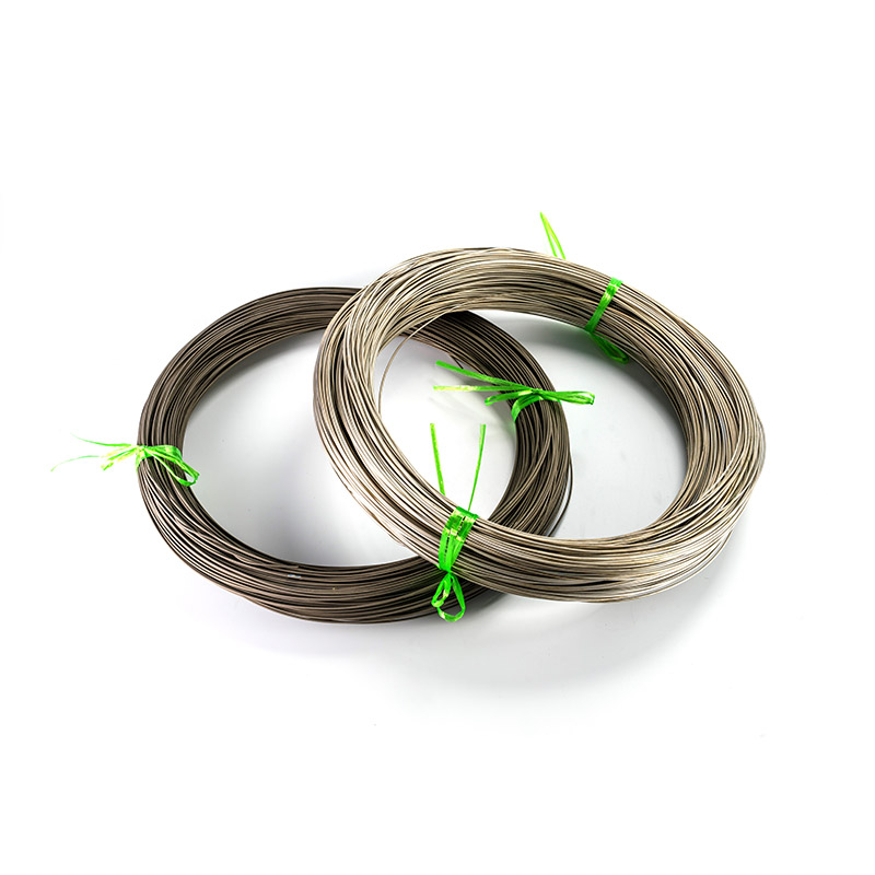
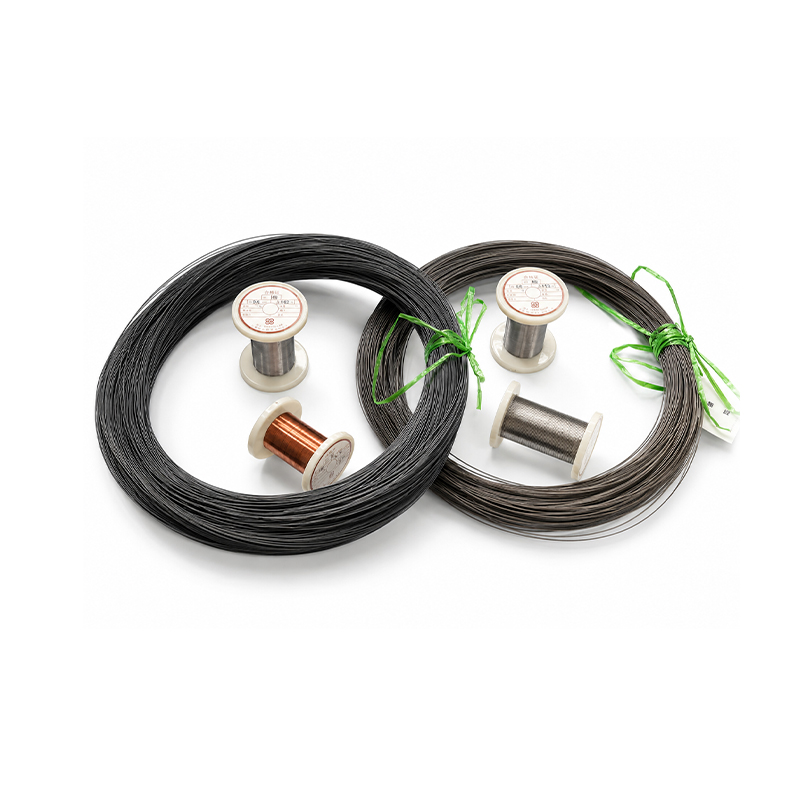
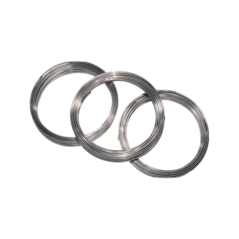
Three practical consequences follow. First, the compensating or extension cable must use alloys matched to the thermocouple type. Ordinary copper wire creates a new junction at the terminal block and at the junction box, and the error grows with the temperature difference along the cable route. Second, every connection is a potential error source: loose terminals, corroded screws and damp junction boxes all add uncontrolled voltages. Third, alloy consistency matters over time, which is why the source of thermocouple alloy wire and compensating cable is a legitimate engineering question rather than a purchasing detail.
Suppliers that control both ends of that chain have an advantage. Xinguo Group, for example, operates alloy, cable and instrument businesses within one group structure, producing thermocouple alloy wire and compensating cable alloys alongside the temperature instruments that read them. For a plant engineer, that matters because a drifting cable batch can be traced back to composition data rather than argued about.
Roughly 41 microvolts per degree Celsius for type K means a 0.1 millivolt wiring error is already 2.4 degrees of apparent temperature. Treat every terminal as a measurement point.
Channel Count, Scan Rate and Memory in Real Applications
Channel count is where most specifications begin and where most misunderstandings start. An 8 channel logger rarely fails a project outright; an 8 channel logger used on a 24 point furnace survey fails quietly, by producing an incomplete map that nobody notices until the report is written. The correct number comes from the physical job, not from the catalogue page.
Scan interval is the second lever. Short intervals capture excursions but consume memory and battery, while long intervals stretch unattended running time but smooth away the events that caused the problem. Memory depth then determines whether you can leave the instrument on site for a weekend or a month. Finally, the physical spread of the measurement points decides whether a single enclosure with long cable runs is realistic or whether distributed nodes make more sense.
The chart below summarises typical channel counts and logging intervals observed across common thermocouple logging jobs. It is intended as a planning starting point rather than a rule, because every plant has its own tolerance for spares.
Typical channel counts by application (bar length is proportional to channel count)
Battery and power electronics thermal testing (about 1 second)48 channels
Petrochemical pilot reactor mapping (about 5 seconds)32 channels
Heat treatment furnace survey (about 10 seconds)24 channels
Cement kiln and mill bearing monitoring (about 30 seconds)16 channels
Cold storage and transport monitoring (about 60 seconds)12 channels
Food retort and steriliser validation (about 10 seconds)10 channels
Laboratory material and alloy testing (about 2 seconds)8 channels
Values reflect common engineering practice for each application type and should be adjusted for local spares policy and reporting requirements.
The pattern in the chart is not accidental. Applications at the top combine many measurement points with fast thermal events, so they need both high channel count and short intervals. Battery and power electronics testing falls into this group because cell level temperatures can move several degrees in seconds, and a single missed spike can be the entire point of the test. Pilot reactors sit just below because they combine many points with moderate thermal inertia.
Furnace surveys sit in the middle. Twenty four channels is enough to cover a multi zone furnace with entry, exit and load thermocouples, and a ten second interval is fast enough to see a control cycle without generating unmanageable files. Kiln and mill bearing monitoring needs fewer channels because the points of interest are fixed and well known, and the thirty second interval suits the slow thermal mass of the equipment.
Cold chain work sits lower again, which surprises buyers who assume monitoring always benefits from more channels. A refrigerated trailer or a cold room may need only a handful of points, but it needs weeks of unattended operation, so memory depth and battery life dominate the specification while channel count does not. Retort validation returns to shorter intervals because the sterilisation profile itself is the product of interest.
Laboratory material testing often uses fewer channels than plant work but demands the fastest sampling, because alloy and coating behaviour is being characterised rather than controlled. This is where a logger that supports a two second interval and per channel thermocouple type selection earns its price.
Memory planning is simple arithmetic that is rarely done. Thirty two channels logged every five seconds produces 384 samples per minute, or about 23,000 per hour. Across a three day trial that approaches 1.7 million samples, so a unit with a one million sample buffer will overwrite the start of the test unless a memory card is fitted or the interval is relaxed.
A practical rule is to specify 30 to 50 percent more channels than the current job requires. Spares absorb the failed thermocouple in the middle of a survey, the extra point added halfway through a trial, and the ambient reference that nobody remembered to include in the plan.
Match the logger to the thermal speed of the process, not to the size of the plant. Fast events require short intervals, long unattended runs require memory, and spare channels are cheaper than repeat visits.
Common Types of Multi Channel Thermocouple Data Logger
Once the measurement requirement is clear, the hardware choice usually narrows quickly. Five architectures cover nearly all industrial and laboratory thermocouple logging work, and the deciding factor is almost always the physical layout of the measurement points rather than the software features.
Comparison of the five logger architectures most often used for thermocouple measurement; the correct choice is normally driven by layout, environment and record keeping needs.
| Type |
Best fit |
Strengths |
Limits |
| Portable standalone logger |
Field surveys, commissioning, troubleshooting |
Battery powered, fast to deploy, easy to move |
Fewer channels, limited alarm integration |
| Modular rack system |
Permanent plant monitoring |
Expandable, strong isolation, easy module service |
Needs panel space and organised wiring |
| Wireless node network |
Spread out assets, cold rooms, warehouses |
Low cabling cost, remote read out |
Battery management and radio path planning |
| Panel mount paperless recorder |
Control rooms and compliance records |
Local display, chart replay, historian features |
Higher cost per channel, larger footprint |
| PC based USB system |
Laboratory and research work |
High speed, flexible analysis software |
Depends on a PC and on careful grounding |
Portable units dominate commissioning and troubleshooting because they travel to the problem. Modular systems dominate permanent installations because a failed module is swapped in minutes without disturbing the rest of the plant. Wireless nodes make sense where cable installation would cost more than the instrumentation itself, though they trade that saving for battery and radio path maintenance.
Panel mounted recorders remain the standard where a control room operator must see trends live and where printed or archived records are a compliance requirement. PC based systems remain the tool of choice in laboratories, where the acquisition hardware is inexpensive but the analysis software carries the real value.
Choose the architecture that matches the physical layout of your measurement points. Cable runs, not software menus, determine which logger type succeeds.
Wiring and Installation Practices That Protect the Data
Most bad temperature datasets are not caused by a defective logger. They are caused by ordinary installation shortcuts that seemed harmless at the time. The following practices prevent the majority of them.
- Use compensating or extension cable whose alloy matches the thermocouple type, and keep the type consistent from tip to terminal.
- Observe polarity at every junction. Reversed type K or type J pairs produce falling readings that look like sensor failure.
- Route thermocouple cabling away from variable frequency drive output cables and motor leads, and cross power cables at right angles where crossing is unavoidable.
- Ground cable shields at one end only, usually at the logger end, to avoid circulating currents.
- Keep terminal blocks clean, dry and correctly torqued, since a loose screw is an uncontrolled junction.
- Use isothermal terminal blocks where cold junction sensing takes place so that all terminals sit at a similar temperature.
- Respect the temperature limits of the extension cable itself; standard PVC insulated compensating cable is not suitable close to a furnace opening.
- Label every channel physically and record the map in the project file, because an unlabelled 24 point survey is a 24 point guess later.
- Allow a settling period after installation before trusting readings, particularly where sensors are clamped or cemented to surfaces.
- Document sensor attachment method for each point, since attachment dominates response time for surface measurements.
The settling point is often underestimated. A thermocouple cemented to a pipe surface and a thermocouple inserted into a thermowell respond at completely different speeds. When a survey shows one point lagging behind the rest, the cause is usually attachment rather than the input channel, and knowing the installation method avoids a wasted maintenance call.
Correct alloy, correct polarity, sensible routing and a written channel map eliminate most temperature logging errors before a single sample is recorded.
Choosing a Multi Channel Thermocouple Data Logger Step by Step
A structured selection process takes less than an hour and prevents expensive late changes. Work through the following sequence in order, because each step constrains the next.
- List every measurement point with its expected temperature range and required accuracy.
- Confirm the thermocouple types in use and check that the logger supports each type individually per channel.
- Define the shortest event you must capture, then set the logging interval to at least twice as fast.
- Calculate memory requirements for the longest unattended run and add a safety margin of double.
- Check the electrical environment for drives, welders and high current cabling, then decide whether isolated inputs are mandatory.
- Review the ambient conditions at the installation point, including summer temperature, humidity, dust and washdown.
- Decide how data will be retrieved and archived, and whether alarms must trigger action on site.
- Confirm that software exports a format your quality system accepts, and test that claim during the trial period.
- Ask the supplier for a calibration certificate and a statement of cold junction accuracy at the intended ambient temperature.
- Add spare channels, spare thermocouples and spare compensating cable before placing the order.
Step nine is frequently skipped, yet it is the one that determines whether the record is usable in a dispute. Cold junction performance quoted at 25 degrees Celsius is not the same as performance at 45 degrees Celsius in a plant room, and a supplier who understands the application will quote the realistic figure.
Specify from the measurement outward: points, types, event speed, environment, then instrument. Selecting the logger first almost always ends in compromised data.
Maintenance, Verification and Calibration Routines
A logger that is never verified is an opinion rather than a record. The routines below keep a multi channel system credible across years of service, and they are inexpensive compared with the cost of a failed audit.
Routine checks
- Inspect terminal blocks and junction boxes for corrosion, moisture and loose screws at each scheduled shutdown.
- Check battery condition and replace before capacity falls below the planned unattended run length.
- Download and archive stored data regularly, then confirm the archive opens correctly on a different machine.
- Verify the clock against a reference source, since timestamps carry as much weight as temperatures in a dispute.
Verification and calibration
- Perform an ice point or dry block check on a rotating sample of channels at defined intervals.
- Compare a reference thermocouple against a working channel in the same isothermal block to detect drift.
- Record ambient temperature at the terminal block during verification, because cold junction performance depends on it.
- Keep calibration history per channel, not per instrument, so that a drifting channel is identified rather than averaged away.
Twelve month verification intervals suit most permanent installations, while survey instruments used on customer sites are often verified more frequently or before each critical project. The interval should follow the consequence of being wrong, not a default calendar entry.
Verification is per channel, not per instrument. A single drifting input will drag an entire dataset into question if it is never isolated.
Buying From a Manufacturer, Supplier or Wholesaler
Thermocouple logging hardware is often bought through a wholesaler or distributor, but the responsibility for accuracy usually belongs to the manufacturer behind the product. Understanding who actually makes what changes the questions you ask.
A manufacturer controls alloy composition, terminal design and firmware behaviour, so it can answer technical questions about drift, cold junction sensing and thermocouple type support. A supplier or wholesaler controls stock, lead time and commercial terms, but may not be able to interpret a furnace survey requirement. A good purchasing decision usually combines both, with the manufacturer providing the technical commitment and the supplier providing availability.
Questions worth asking before ordering
- Which thermocouple types are supported on each channel, and can types be mixed within one instrument?
- What is the stated cold junction accuracy, and at which ambient temperature is it specified?
- Is isolation channel to channel, or only between input groups and ground?
- What is the memory depth and what happens when the buffer fills?
- Is a calibration certificate supplied, and can additional traceable certificates be ordered?
- What is the stated tolerance and grade of the thermocouple alloy wire and compensating cable supplied with the system?
- What is the lead time for spare modules, connectors and cable?
- Is technical support available in the language of the installation team?
Lead time for spares deserves more attention than it usually receives. A plant that standardises on one logger family and keeps two spare modules on the shelf avoids a month of unmonitored operation after a single failure. Buyers negotiating with a wholesaler should ask specifically about spare parts availability rather than only about unit price.
Buy the measurement chain, not just the box: instrument, cable alloy and spare module availability together determine whether the system still works in year three.
Product families worth reviewing for thermocouple measurement systems
Xinguo Group operates alloy, cable and instrument businesses within a single group structure, which allows a measurement chain to be sourced with matching materials and instruments.
- Thermocouple alloy wire for sensor and junction construction
- Thermocouple compensating cable alloy wire for extension runs
- Constantan, manganin, nickel chromium and pure nickel resistance alloys
- Industrial resistance temperature detectors, including armoured, explosion proof, multi point, anti corrosion and power station types
- Pressure instruments, flow meters, level instruments and instrument materials
Engineers specifying logging systems can request material composition data and instrument documentation from a single supplier, which simplifies traceability across a project.
Frequently Asked Questions
How many channels does a multi channel thermocouple data logger really need?
Start from the number of meaningful measurement points, then add 30 to 50 percent headroom for spares and ambient references. A 16 point furnace survey is normally specified with 24 channels, and a 40 point reactor mapping exercise with 48 channels. Fewer channels than points means a repeat visit, which costs more than the extra inputs.
Can a multi channel thermocouple data logger accept any thermocouple type?
Most quality instruments support type K, J, T, E, N, S, R and B, but support is often configured per channel rather than globally. Confirm that types can be mixed within one unit, and check that the internal cold junction compensation remains accurate when dissimilar types share a terminal block.
Why is cold junction compensation accuracy so important?
Because it applies to every channel at once. The instrument measures the temperature of its own terminals and adds the equivalent voltage before converting to temperature. An error of 1 degree Celsius in that reference shifts every recorded value by approximately 1 degree, which can consume a significant share of a process tolerance.
Is it acceptable to extend thermocouples with ordinary copper cable?
No. Copper extension creates additional junctions at the terminal block and at any intermediate connector. The resulting error depends on the temperature difference along the route, so it may look negligible in winter and become significant in summer. Always use compensating or extension cable whose alloy matches the thermocouple type.
What logging interval should I choose?
Set the interval to at least twice as fast as the fastest event you need to see. Furnace surveys often work well at ten seconds, battery thermal tests at one second, and cold chain monitoring at sixty seconds. A shorter interval than necessary only consumes memory and battery capacity.
How often should a thermocouple logger be calibrated?
Twelve months is a common default for permanently installed equipment, with more frequent verification for survey instruments used on customer sites. The interval should reflect the consequence of an incorrect reading rather than a fixed policy applied to every application.
Can one logger record both thermocouples and resistance temperature detectors?
Some models offer universal inputs that accept both, others require separate modules. Universal inputs improve flexibility, but check that switching between thermocouple and resistance measurement does not compromise the accuracy specification you rely on for the thermocouple channels.
What is the difference between a data logger and a paperless recorder?
A data logger acquires and stores measurements for later download, while a paperless recorder adds a local display, live trends and often historical review on the panel itself. Recorders suit control rooms and compliance environments; loggers suit field surveys and unattended trials.
Should I choose wireless or wired channels?
Wireless nodes reduce cabling cost when measurement points are spread across a large site, but they introduce battery management and radio path planning. Wired systems remain simpler for compact installations and where power is already available at the measurement point.
What documentation should a supplier provide?
At minimum, a calibration certificate for the instrument, stated cold junction accuracy at defined ambient conditions, alloy composition or tolerance grade for supplied thermocouple wire and compensating cable, and a channel configuration record if the unit is delivered pre-programmed for your project.
Most specification questions resolve to three issues: how many points, how fast must they be sampled, and how accurate must the reference junction be.
A well specified multi channel thermocouple data logger does not attract attention. It sits in a panel or on a bench, records a defensible dataset, and answers questions months later when someone asks what the process actually did. Getting there requires attention to the parts that are easy to overlook: matched compensating cable, honest cold junction accuracy, isolated inputs and a channel map that survives the project.
Work from the measurement outward, verify per channel rather than per instrument, and treat spare capacity as insurance rather than waste. Those habits cost very little at specification time and save a great deal when a record has to stand up to scrutiny.



 INQUIRY
 English
 عربى
عربى русский
 中文简体
中文简体