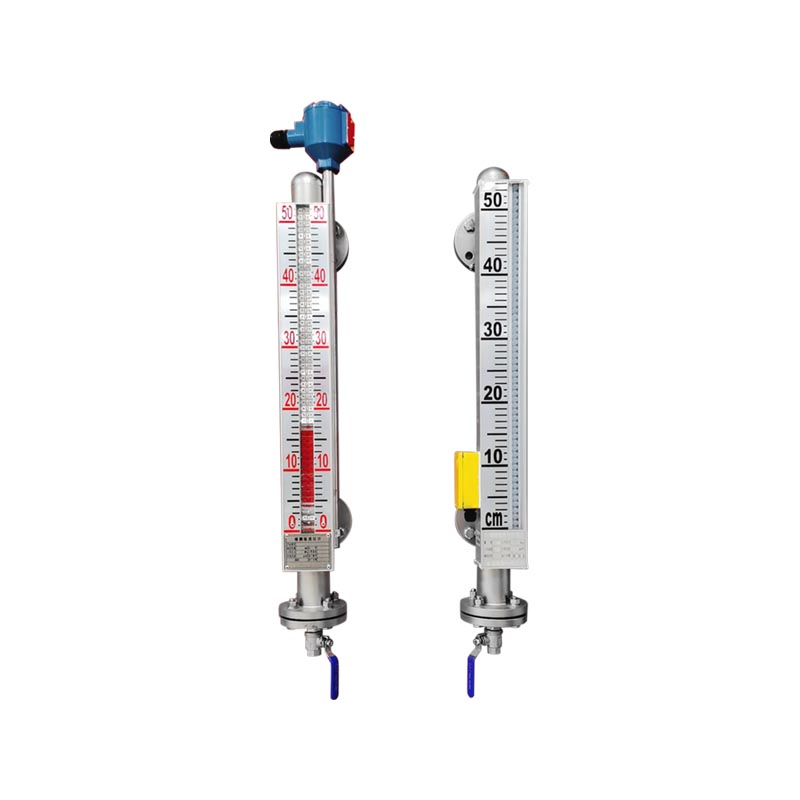
 XGUHZ-50C series of magnetic float level meter
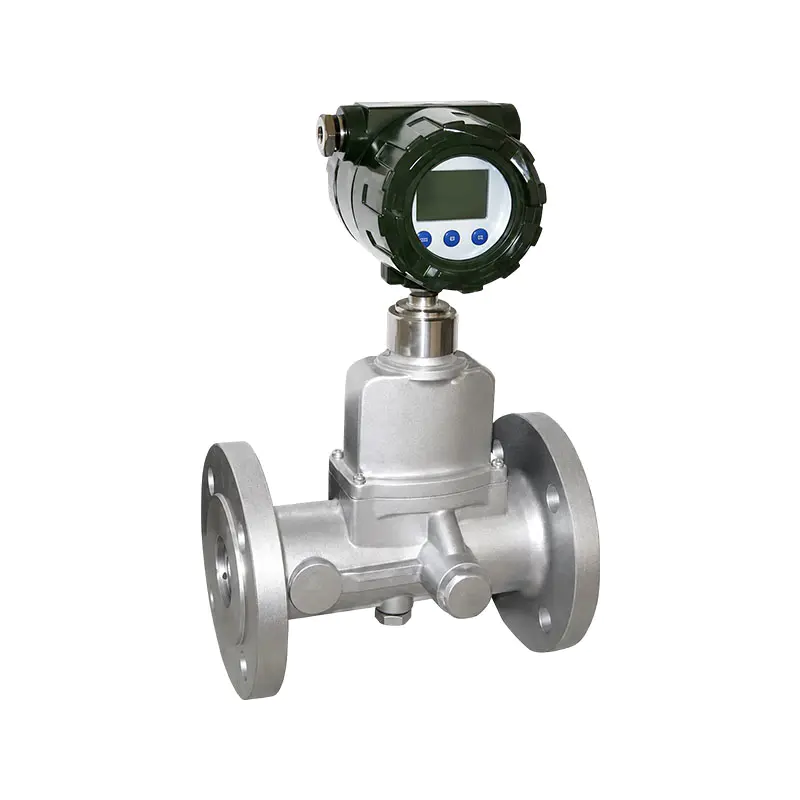 XG-LUX Intelligent Swirl Flow Meter
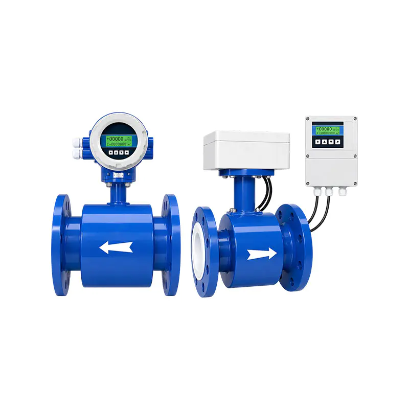 XG-LDE Intelligent Electromagnetic Flow Meter
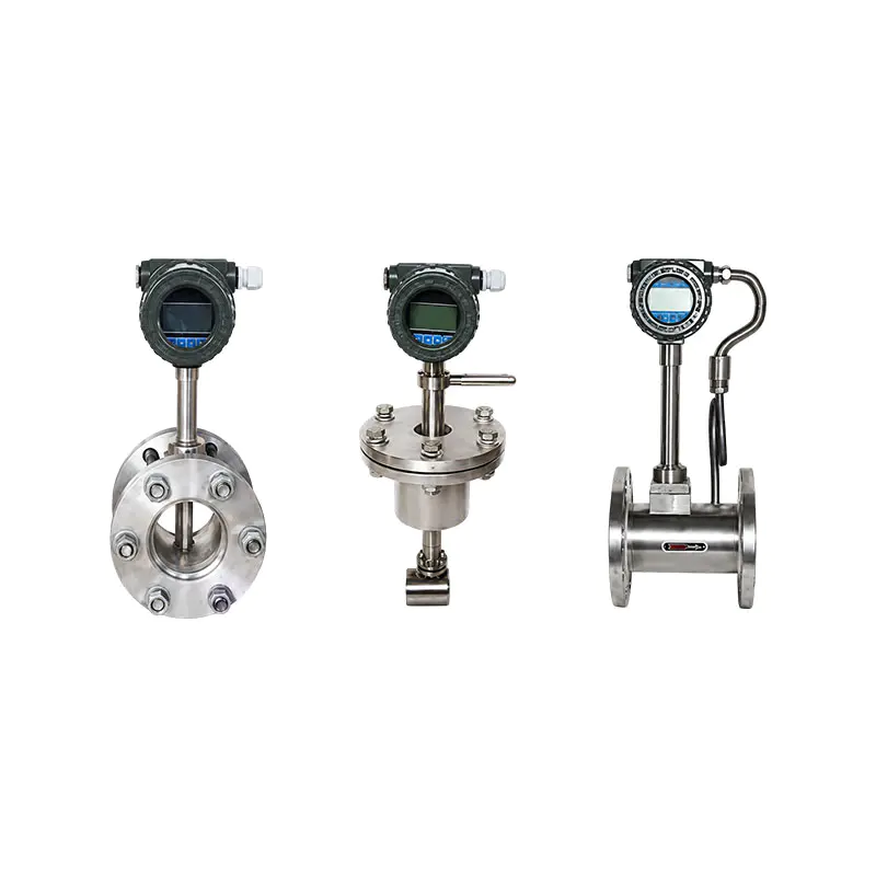 XG-LUGB series intelligent vortex flowmeter
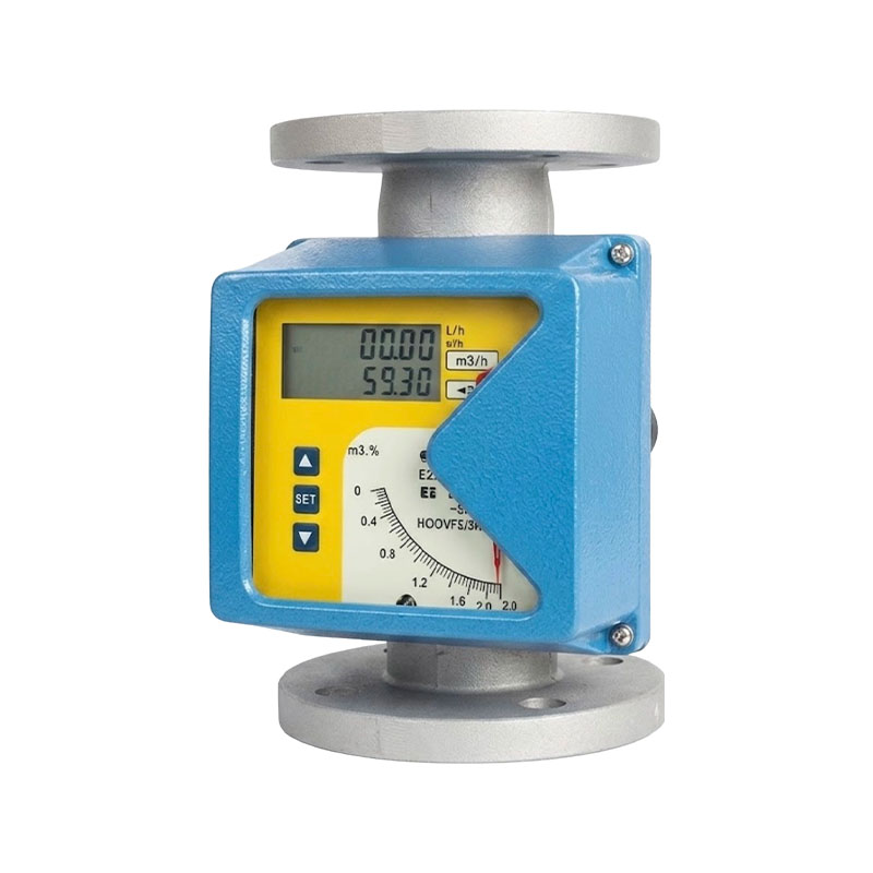 XG-JF Series Metal Float Flow Meter
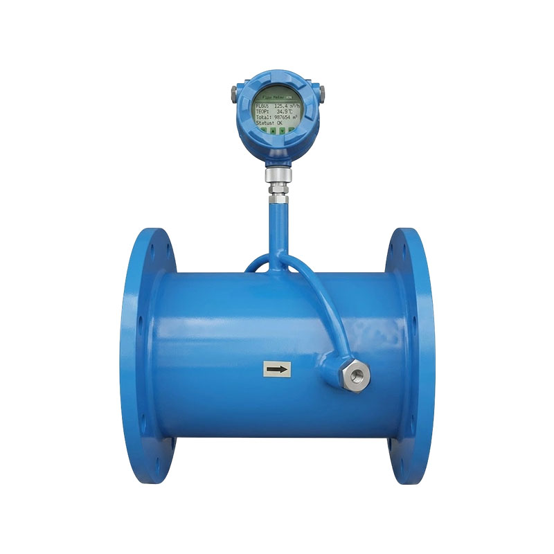 XG-CSL Intelligent Ultrasonic Flow Meter
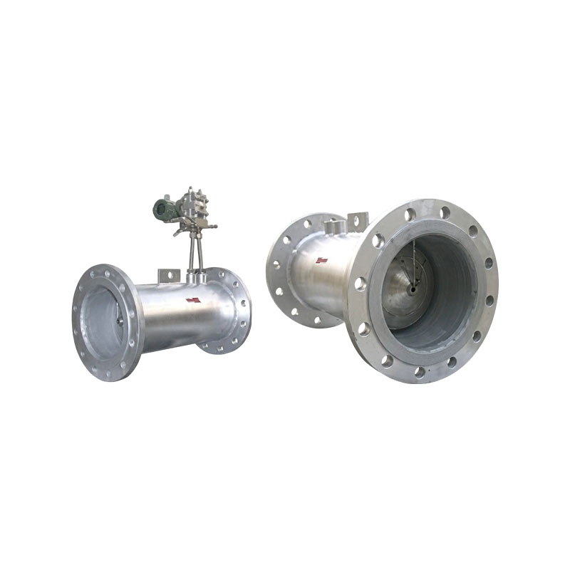 XG-V Series V-notch Flow Meters
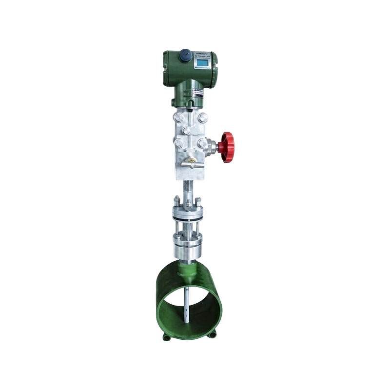 XG-W type Velbar flowmeter
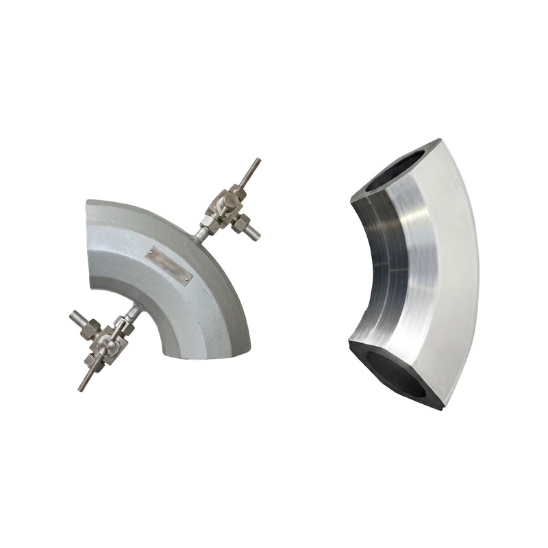 XG-WG bend tube flowmeter
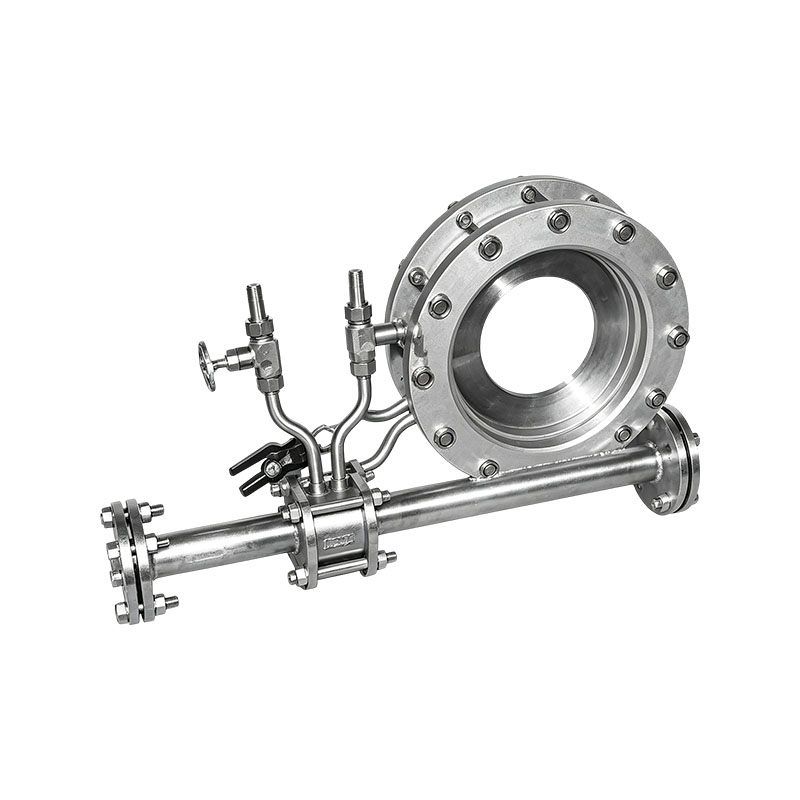 XG-LG Series Flow Measurement Throttling Device
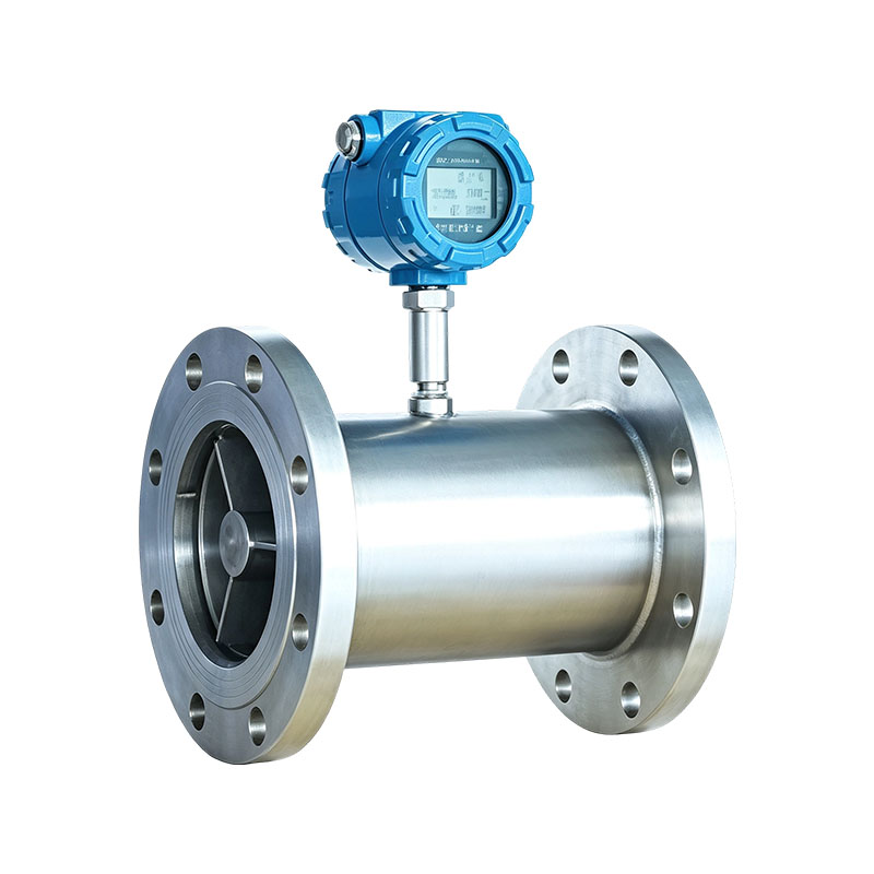 XG-GY series liquid turbine flowmeter
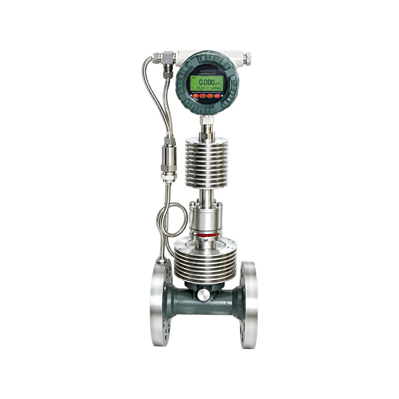 XG-DBL Type Dynamic Pressure Differential Flow Meter
Product definition:
A flowmeter is a measuring instrument used to measure the volumetric or mass flow rate of a fluid passing through a certain section of a pipeline (or open channel) in a unit of time. It is one of the most basic and commonly used measuring instruments in industrial production process control, trade handover measurement, energy management, and environmental monitoring.
Core features:
The measurement object covers liquids, gases, and vapors; There are various measurement principles, and different principles determine their accuracy, range ratio, applicable medium, and operating conditions; Usually composed of sensors and transmitters (signal processing part), it outputs 4-20mA, pulse, or digital signals (HART, RS485, Modbus, etc.).
Core advantages:
1、 Accurate measurement, supporting trade settlement and cost accounting. High-precision measurement of fluid volume/mass flow rate, with controllable errors, widely used for trade handover measurement and in-plant cost accounting of water, gas, steam, and oil products. It is a hard basis for calculating how much is used.
2、 Real-time online, achieving automation and remote monitoring
Continuous online measurement and output of standard signals (4-20mA, pulse, HART, RS485, etc.), which can be directly connected to DCS/PLC and IoT platforms to achieve automated control, data acquisition, remote meter reading, and alarms, reducing manual duty.
3、 Wide range, strong adaptability to working conditions, covering multiple media
Full coverage of liquids, gases, and vapors; Electromagnetic, vortex, ultrasonic, and mass principles each have their own strength, and can cope with various working conditions such as conductivity differences, corrosive media, high temperature and high pressure, large diameters, and non-full pipes, solving one type of scenario with one table.
4、 Energy conservation and consumption reduction, assisting in energy and cost management
By accurately measuring and detecting leaks, optimizing process ratios, and finely managing energy sources such as water, electricity, gas, and steam, it directly brings about energy conservation, consumption reduction, and cost optimization, resulting in significant long-term returns.
Main application industries:
1、 Petroleum, Natural Gas, and Chemical Industry
Exploration and extraction, refining, oil and gas pipeline transportation, storage and transportation, and trade handover measurement, as well as precise measurement of crude oil, refined oil, natural gas, and chemical raw materials, are the " measurement heart" of the energy industry chain.
2、 Electricity, Metallurgy, and Energy Power
Boiler feedwater, steam flow rate, generator cooling water, and gas and liquid metering in steel metallurgy processes are key monitoring points for energy balance accounting and process control, and are essential for energy conservation and consumption reduction.
3、 Water treatment and municipal water supply and heating
Measurement of incoming and outgoing water from water plants, sewage treatment, municipal pipeline supply, and centralized heating and heat exchange stations, supporting zoning measurement, pipeline leakage analysis, and volume-based charging.
4、 Food, medicine, and environmental monitoring
Flow data collection for hygiene-grade process measurement in food and beverage, pharmaceutical, as well as environmental online monitoring scenarios such as flue gas desulfurization and wastewater discharge.
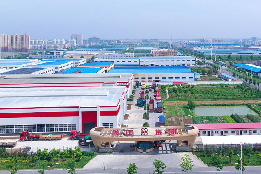
Founded in
Cover an area of
Experienced employees
Building area

A heat-treatment line that replaced its protection tubes every six weeks did not have a thermocouple problem. It had a ceramic problem. The elements came out of service clean and unbroken, yet the tubes had cracked, spalled or bowed, and the drift that followed belonged to the t...

The first sign that something is wrong with a thin film RTD is rarely a dramatic failure. It is a slow disagreement with a neighbouring sensor, a reading that creeps during a heat-up cycle, or a batch trend that no longer matches the recipe. In one case, a food processor replace...
A dairy processor in eastern China spent three weeks chasing a pasteurizer fault that turned out to be one crossed thermocouple extension wire inside a junction box. The recorder kept writing believable numbers the whole time, which is precisely why the investigation took so lon...
A heat-treat line running at 900 degrees Celsius will usually consume a Type K thermocouple in eight to fourteen months. The same probe sitting in a clean water loop at 90 degrees Celsius often survives eight years or more. Nothing about the two probes looks different on a datas...
Flow meters are instruments that measure how fast a fluid is moving through a pipeline, channel or duct, or how much fluid has passed through over a given period. Inside the meter, a physical property of the moving fluid, such as its speed, the pressure difference it creates, or its momentum, gets turned into an electrical or mechanical signal that can be read on site or sent back to a control room. Because liquids, gases and steam all behave differently as pressure and temperature change, flow meters are built around several different physical principles, including electromagnetic induction, vortex shedding, ultrasonic transit time, Coriolis force, and differential pressure.
On a typical process line, a flow meter usually sits close to other field instruments, such as pressure transmitters and temperature sensors, so its readings can be compared against what else is happening in the process. Which flow meter fits best depends heavily on what the fluid actually is, how accurate the reading needs to be, and what the pipeline itself allows for in terms of space and layout. When the right instrument is chosen for the job, it helps keep production steady, supports energy accounting, and gives operators the visibility that automated manufacturing and utility systems rely on.
Every flow meter has a set of technical characteristics that determine whether it fits a given job. These are usually listed on the instrument datasheet, and it helps to look at them together rather than one at a time, since doing well on one trait often means giving up a little ground on another. The list below groups the factors most commonly checked during flow meter selection into two categories: how the instrument performs, and how well it fits into the surrounding plant and control system.
In short: accuracy and rangeability describe how precisely and how broadly a meter measures, pressure loss and media adaptability describe how well it fits the physical process, and output signal, installation needs and reliability describe how well it fits the surrounding control system. Weighing all seven together, instead of focusing on just one, is generally what leads to a well-matched flow meter.
The chart below lines up several common flow meter types by how much their reading typically deviates from the true value. Accuracy deviation is given as a percentage, and a smaller number means a tighter, more precise reading. These figures reflect commonly referenced industry ranges rather than fixed guarantees, since real performance still depends on installation quality, fluid conditions and how well the instrument is calibrated. The comparison is meant to give a general feel for where each measurement principle usually sits on the precision scale. Reading it alongside the other selection factors on this page helps narrow the field before settling on a final specification.
As the chart shows, Coriolis mass flow meters usually sit at the tightest end of the precision scale, with deviation figures often quoted around ±0.15%, which is one reason this technology gets picked for custody transfer and high-value fluid metering. Electromagnetic and turbine flow meters come next, both commonly quoted near ±0.5%, which suits general process control work that still needs a reasonably tight tolerance. Ultrasonic and vortex flow meters typically land around ±1.0% deviation, a level that covers most utility and industrial monitoring needs, and clamp-on ultrasonic designs manage this without ever touching the fluid. Differential pressure meters built around an orifice plate tend to sit closer to ±1.5%, which reflects the square-root relationship between pressure difference and flow speed becoming more pronounced at lower flow rates. Variable area meters, or rotameters, usually show the widest deviation of the group, often quoted near ±2.0%, which is fine for a quick visual check but less suited to tight process control. It is worth keeping in mind that an accuracy figure only really means something once it is paired with a defined range ratio, since a meter can look very accurate at its rated flow point while performing poorly outside that range. Picking a flow meter purely because it has the lowest published deviation figure, without also checking rangeability, media compatibility and installation constraints, often leads to a mismatch between the instrument and the actual process. For that reason, accuracy is best treated as one input among several rather than the single deciding factor.
Flow meters fall into families based on the physical principle they use to sense fluid movement. Each family carries its own mix of accuracy, media compatibility and installation needs, which is why a single industrial site often runs several different flow meter types at once. The subsections below walk through how each of the most common types works and where it tends to be used.
Electromagnetic flow meters work on Faraday's law of electromagnetic induction. A magnetic field is generated across the pipe, and as a conductive fluid passes through it, the fluid induces a small voltage that the meter measures. Because that voltage is proportional to the average fluid velocity, the meter gives a linear reading across a wide flow range without putting anything inside the pipe to block the flow. This design only works with electrically conductive liquids such as water, wastewater and many process chemicals, and it cannot be used for gases, steam, or non-conductive fluids like most hydrocarbons.
Turbine flow meters place a small rotor in the flow path. The moving fluid spins the rotor at a rate that tracks its velocity, and a pickup coil detects the rotation and turns it into a pulse signal. Turbine meters offer good accuracy and a fast response for clean, low-viscosity liquids and gases, but the moving rotor wears over time, and particles in the fluid can shorten bearing life or slowly throw off the reading.
Vortex flow meters rely on the Karman vortex street effect: a small bluff body placed in the flow path causes alternating swirls, or vortices, to peel off downstream at a frequency tied to the flow speed. A sensor picks up that shedding frequency and converts it into a flow reading. Vortex meters have no moving parts, work with liquids, gases and steam, and handle a fairly wide temperature range, though they need a minimum flow speed to produce a stable signal, which makes them less suited to very low flow rates.
Ultrasonic flow meters measure the tiny difference in travel time between ultrasonic pulses sent with and against the direction of flow, or, in some designs, measure the Doppler frequency shift caused by particles or bubbles carried in the fluid. Clamp-on versions mount on the outside of the pipe, so they can be installed or serviced without cutting into the pipeline or stopping the process. That non-intrusive quality makes ultrasonic meters a good fit for large-diameter pipelines and for sites where shutting down the process to install a meter would be disruptive.
Coriolis flow meters measure mass flow directly by picking up a slight twisting motion, known as the Coriolis effect, in a vibrating tube as fluid moves through it. Because the reading is based on mass rather than volume, Coriolis meters are largely unaffected by changes in fluid density, pressure or temperature, which supports very high accuracy. The same design can measure fluid density at the same time, which is one reason it is a common choice for custody transfer and high-value fluid metering, even though the instrument tends to be heavier and costlier than other designs.
Differential pressure flow meters, most often built around an orifice plate, narrow the flow path slightly and measure the pressure drop this creates. Because flow rate is proportional to the square root of that pressure difference, the design is simple, well understood, and works across a wide range of clean liquids, gases and steam, though accuracy drops off noticeably at low flow and the narrowed opening creates a permanent, small pressure loss.
Variable area flow meters, better known as rotameters, use a tapered glass or metal tube in which a small float rises or falls depending on the flow rate, with the float's position read straight off a graduated scale. Because it needs no external power for a basic visual reading, this design is simple and low-cost for general monitoring, though it is normally mounted vertically and gives less precise readings than electronic alternatives.
Rangeability, sometimes called turndown ratio, describes how wide a span of flow rates a given instrument can measure while staying inside its rated accuracy. The chart below shows typical rangeability figures for the flow meter types covered above, given as a ratio between the highest and lowest flow rate the instrument can reliably measure. A higher ratio means one instrument can handle a broader range of operating conditions without needing to be resized or swapped out. This matters most for processes where flow rate swings noticeably across a production cycle. Reading rangeability together with accuracy gives a fuller picture of how an instrument will hold up over the long run.
Coriolis mass flow meters usually offer the widest rangeability of the group, with figures often quoted as high as 100:1, which fits with mass measurement through tube deformation staying stable across a very broad flow span. Electromagnetic and ultrasonic flow meters both commonly reach a turndown near 50:1, giving stable readings across a wide operating window without any moving parts involved. Turbine flow meters generally sit around 20:1, which is enough for many general process jobs but narrower than electromagnetic or ultrasonic options. Vortex meters typically land near 15:1, limited by the minimum speed needed to keep a detectable vortex shedding signal going. Rotameters commonly offer a turndown around 10:1, fine for steady flow monitoring but less flexible where flow rates vary a lot. Orifice plate meters usually show the narrowest rangeability of the common types, often quoted around 4:1, a direct result of the square-root relationship between pressure difference and flow rate, which makes measurement uncertainty grow quickly at reduced flow. When a process is expected to run across a wide range of flow conditions, choosing an instrument with narrow rangeability can leave the meter working outside its accurate range for long stretches of time. On the other hand, specifying far more rangeability than a stable, narrow-range application actually needs usually just adds cost without adding real benefit. Matching rangeability to how the process actually behaves, rather than defaulting to whichever figure is highest, tends to give the best overall value. This is one reason flow meter selection is usually done alongside a look at historical or expected flow data for the pipeline in question.
Beyond accuracy and rangeability, a handful of other qualities shape how well a flow meter fits a given installation. The radar chart below compares three widely used types, electromagnetic, vortex, and clamp-on ultrasonic, across five qualities: accuracy, media adaptability, low pressure loss, maintenance simplicity, and signal stability. Each quality is scored on a relative scale, and a larger shaded area points to stronger overall performance across the five dimensions shown. This chart is meant to support a well-rounded comparison rather than crown one technology as the best choice in every situation. The relative strengths shown here should always be weighed against the specific fluid and site conditions of the actual project.
The comparison shows that electromagnetic flow meters score strongly on accuracy and signal stability, which fits the straightforward, linear relationship between induced voltage and flow speed, while scoring more moderately on media adaptability because the fluid has to be electrically conductive. With nothing sitting inside the pipe to block flow, they also score well on low pressure loss, and having no moving parts helps their maintenance simplicity score too. Vortex flow meters show a more even spread across all five qualities, solid but not outstanding in each one, which reflects how broadly they apply to liquids, gases and steam without being the top pick in any single category. The small bluff body inside the pipe does cause some pressure loss, which shows up as a moderate score there. Clamp-on ultrasonic flow meters score particularly well on media adaptability and low pressure loss, since mounting on the outside of the pipe means the sensor never touches the fluid and nothing blocks the flow path. Maintenance simplicity also rates well for ultrasonic designs, since there is no wetted part to replace or clean out over time. That said, ultrasonic meters can lose some signal stability when the fluid carries entrained gas bubbles or a lot of solid particles, since that interferes with the transit-time or Doppler measurement. This trade-off is a good illustration of why no single flow meter type wins in every situation; the right technology depends on which of these qualities matters most for a given pipeline, fluid and operating environment. Sites that handle a wide range of process fluids often keep more than one flow meter family on hand for exactly this reason.
Flow meters show up in almost every industrial sector where a fluid needs to be measured, controlled or accounted for. Which type gets used in a given sector usually comes down to the properties of the fluid, how accurate the reading needs to be, and how the piping is laid out. The table below gives a quick reference for common industries and the kinds of measurement they typically need.
| Industry Sector | Representative Measurement Needs |
|---|---|
| Petrochemical Processing | Crude oil, refined products, natural gas, chemical raw material metering, and steam flow measurement in refining processes |
| Water Treatment and Environmental Protection | Tap water distribution, sewage treatment, wastewater discharge, and reclaimed water reuse systems |
| Power Generation | Boiler feedwater, main steam, cooling water, fuel gas, and flue gas desulfurization and denitrification fluid metering |
| Metallurgy and Steel Production | Cooling water circuits, circulating water systems, and combustion-assisting gases such as oxygen and nitrogen |
| Food and Pharmaceutical Processing | Hygienic metering of purified water, beverages, syrups, and other liquids requiring sanitary-grade instrumentation |
| HVAC Systems | Heating and chilled water circuits, along with energy consumption monitoring at heat exchange stations |
| Papermaking and Textile Manufacturing | Process water, pulp slurry, chemical additive, and steam flow control |
| Gas Distribution | Urban gas networks, industrial gas supply, liquefied natural gas terminals, and compressed air systems |
| Marine, Rail Transit, and Laboratory | Fuel consumption monitoring and controlled test flow measurement |
In short: what these sectors share is a need for dependable flow data at a specific point in the process, whether for energy accounting, process control, or hygienic product handling, and the flow meter family that fits each sector best usually follows from how conductive, clean, and pressurized that industry's fluids typically are.
A flow meter rarely sits at one fixed flow rate for its whole working life; flow conditions typically shift throughout a production cycle. The line chart below shows how measurement error changes as flow rate moves from 10 percent up to 100 percent of full scale, comparing an electromagnetic flow meter against an orifice plate differential pressure meter. This comparison brings the earlier discussion of measurement principles down to a practical, visible difference. Seeing this pattern helps explain why certain flow meter types get chosen for applications where flow rates bounce around. The horizontal axis shows flow rate as a percentage of the instrument's full-scale rating, and the vertical axis shows measurement error as a percentage.
The chart shows that the electromagnetic flow meter keeps a fairly flat error line across the whole flow range, staying close to 0.5 percent whether it is running at 10 percent or 100 percent of full scale. That steadiness comes directly from the linear relationship between induced voltage and fluid speed, which does not depend on the square of the flow rate. The orifice plate meter, by contrast, shows a clear rise in error as flow rate drops, moving from around 1.0 percent at full scale up to roughly 4.0 percent at 10 percent of full scale. This comes from the square-root relationship between pressure difference and flow speed, which means a small pressure signal at low flow turns into a comparatively large measurement uncertainty. For processes that run steadily near their design flow rate, this difference may not matter much in practice, since both instrument types can perform well within a narrow operating band. But for processes with batch cycles, start-up and shutdown swings, or seasonal demand changes, the flow rate can spend a lot of time well below the design point, where the gap between these two measurement approaches becomes much more noticeable. This is one practical reason differential pressure meters are often paired with a wider sizing margin, or swapped for vortex, ultrasonic, or electromagnetic alternatives, in applications where low-flow accuracy really counts. Engineers reviewing historical flow data for a given pipeline can use a comparison like this one to judge whether a lower-cost differential pressure instrument will meet their needs across the full operating range, or whether the extra cost of an electromagnetic or ultrasonic meter is worth it for steady low-flow performance.
Picking the right flow meter for a pipeline means checking several related factors together, rather than zeroing in on a single spec like accuracy or price. The points below are commonly reviewed during specification, usually in roughly the order shown.
In practice, these points rarely get evaluated one at a time, since a manufacturer with a broad instrument background can help line up several of them at once. Xinguo Group Co., Ltd. develops temperature, pressure, level, and flow instruments as part of one coordinated product range, which means selection guidance, sensor material choices, and signal output configuration can be reviewed together instead of as separate purchasing decisions. Founded in 1997 and headquartered in Tianchang City, Anhui Province, Xinguo Group Co., Ltd. has built a broad instrumentation and materials business over more than two decades, with a technical team that includes senior engineers and assistant engineers supporting product development and quality control across the company's various product lines. This kind of joined-up approach, backed by an established manufacturing base, tends to help facilities that run multiple instrument types along a single process line and prefer to keep signal protocols and calibration practices consistent across their instrumentation.
In short: media compatibility and accuracy needs generally narrow the field first, flow range and installation constraints narrow it further, and signal output, environment, and maintenance support round out a specification that fits both the process and the facility's long-term operating needs.
The table below pulls together the operating principle, typical accuracy, rangeability, pressure loss behavior, and media suitability for the flow meter types covered on this page. It is meant as a quick reference for early-stage screening, before a more detailed technical review is carried out for a specific pipeline and fluid.
| Flow Meter Type | Operating Principle | Typical Accuracy | Rangeability | Pressure Loss | Media Suitability | Typical Application |
|---|---|---|---|---|---|---|
| Electromagnetic | Faraday electromagnetic induction | ±0.5% | 50:1 | None (no obstruction) | Conductive liquids only | Water, wastewater, process chemicals |
| Turbine | Rotor speed proportional to velocity | ±0.5% | 20:1 | Moderate | Clean liquids and gases | Custody transfer, clean fluid metering |
| Vortex | Karman vortex shedding frequency | ±1.0% | 15:1 | Moderate | Liquids, gases, steam | Steam metering, general process monitoring |
| Ultrasonic (Clamp-on) | Transit-time / Doppler ultrasonic signal | ±1.0% | 50:1 | None (external mount) | Most liquids, large pipe diameters | Large pipelines, non-intrusive retrofit |
| Coriolis | Coriolis force on a vibrating tube | ±0.15% | 100:1 | Moderate to high | Liquids and slurries, mass basis | Custody transfer, high-value fluid metering |
| Orifice Plate (DP) | Differential pressure across a restriction | ±1.5% | 4:1 | High | Clean liquids, gases, steam | General industrial flow measurement |
| Rotameter (VA) | Float position in a tapered tube | ±2.0% | 10:1 | Low to moderate | Clean liquids and gases | Local visual indication, rough monitoring |
As the table shows, no single flow meter type comes out on top in every column at once, which underlines the main point of this page: choosing an instrument depends on which combination of accuracy, rangeability, pressure loss, and media compatibility matters most for the process at hand. Sites that handle several fluid types and process conditions typically keep more than one flow meter family on hand to cover these differing needs.
Good installation has a direct effect on flow meter accuracy, whatever the underlying measurement principle. Most flow meters need a minimum straight pipe run before and after the sensor so the fluid's velocity profile can settle down before it is measured, and this requirement is usually stricter for turbine and orifice plate designs than for electromagnetic or ultrasonic types. The pipe should stay fully filled at the measurement point, since a partly filled pipe lets in air pockets that throw off the reading for most flow meter types. Proper grounding matters a great deal for electromagnetic flow meters, since stray electrical currents in the pipeline can otherwise interfere with the tiny induced voltage signal. Vibration isolation and secure mounting help protect vortex and turbine sensors from mechanical stress that could affect their calibration over time.
Routine maintenance varies by flow meter type but usually includes periodic checks of any wetted components, verifying zero and span calibration, and cleaning any surfaces that touch the process fluid. Turbine and rotameter designs benefit from regular checks of their moving parts, since mechanical wear is the main cause of accuracy drift in these designs over time. Electromagnetic, vortex, and clamp-on ultrasonic flow meters, none of which have moving parts in the wetted path, generally need less mechanical upkeep, though electrode fouling in electromagnetic meters and transducer coupling in ultrasonic meters are still worth checking on a schedule. Differential pressure instruments should have their impulse lines checked periodically for blockage or leaks, since these lines directly affect the pressure signal reaching the transmitter.
A sudden or gradual mismatch between the flow meter reading and known process facts, such as a tank level change or a batch quantity, is often the first sign that something is off. Signal noise or instability usually points to entrained air, cavitation, or electromagnetic interference from nearby equipment, while a steady but wrong reading can point to sensor fouling, calibration drift, or a partly blocked flow path. Checking installation conditions against the original design is usually the first troubleshooting step, before touching any calibration settings.
In short: good installation prevents many accuracy problems before they start, routine inspection catches wear or fouling early, and a clear troubleshooting order, checking installation before touching calibration, generally resolves reading problems faster.
Accuracy is how closely a flow meter reading matches the true flow value, usually given as a percentage of the reading or of full scale. Repeatability is how consistently the instrument gives the same reading under unchanged conditions, without necessarily saying how close that reading is to the true value. An instrument can show high repeatability while still carrying a calibration offset that affects its overall accuracy.
Some flow meter types, including vortex and certain differential pressure designs, can be used for both liquids and gases, though sizing and calibration differ between the two. Others, such as electromagnetic flow meters, only work with electrically conductive liquids and cannot be used for gas measurement. It is worth checking the manufacturer's specification for the intended fluid before finalizing a choice.
Recalibration intervals depend on the flow meter type, the fluid being measured, and how critical the application is, with many industrial sites following a schedule that ranges from yearly to every few years. Custody transfer or regulatory reporting applications usually follow a more frequent inspection schedule than general process monitoring points. Looking at the historical calibration drift for a specific instrument model can help set a sensible interval for a given site.
Bends, valves, and other pipe fittings disturb the velocity profile of the fluid, creating turbulence or unevenness that can carry on for some distance downstream. Most flow meters are calibrated assuming a stable, even velocity profile at the point where they measure, so too little straight pipe before or after the meter can introduce error even when the instrument itself is working correctly.
Signal instability often comes from entrained air or gas bubbles in liquid service, cavitation near valves or pumps, electromagnetic interference from nearby motors or variable frequency drives, or mechanical vibration affecting the sensor. Pinning down the exact cause usually means checking installation conditions, process operating parameters, and the electrical environment around the instrument.
Xinguo Group Co., Ltd. develops and produces flow instruments alongside temperature, pressure, and level instrumentation, supporting process industries including power, petrochemical, metallurgy, and water treatment. With roots going back to 1997 and a manufacturing base in Tianchang City, Anhui Province, the company also produces cables, valves, and related automation equipment used across these same industries. This broad product range allows flow measurement needs to be reviewed alongside related instrumentation requirements within the same engineering process, which can be useful for facilities coordinating multiple instrument types across a single project.



 INQUIRY
 English
 عربى
عربى русский
 中文简体
中文简体
