A 4-wire RTD is the most accurate resistance temperature detector configuration because it completely removes lead wire resistance from the temperature measurement. In power stations, chemical plants, pharmaceutical facilities, and calibration laboratories, that difference decides whether a loop controls within ±0.1°C or drifts several degrees as cable length, ambient temperature, and terminal conditions change. For instrument technicians, plant engineers, wholesalers, and procurement teams, understanding the construction, wiring rules, accuracy classes, and practical trade-offs of a 4-wire RTD makes it far easier to specify the right sensor assembly from a competent temperature instrument manufacturer. This guide explains the operating principle, wiring diagrams, comparison with 2-wire and 3-wire RTDs, accuracy classes, probe types, selection rules, maintenance practice, and purchasing considerations, with a strong focus on industrial B2B buying decisions.
An RTD is a temperature sensor whose electrical resistance changes predictably with temperature. The most common sensing element is platinum, standardized under IEC 60751, with a nominal resistance of 100 ohms at 0°C (Pt100) or 1000 ohms (Pt1000). The "4-wire" designation means that four conductors run between the sensing element and the measuring instrument, arranged as two pairs in a Kelvin connection. Two of the wires supply a constant excitation current to the element, while the other two are used solely to measure the voltage drop across the element.
The concept of measuring temperature by resistance goes back to Sir William Siemens in the nineteenth century, and platinum quickly became the preferred material because of its chemical stability, repeatability, and wide usable temperature range. Today the platinum RTD is the international reference standard for industrial temperature measurement between roughly -200°C and 600°C. The 4-wire configuration, often called a 4-terminal or Kelvin sensing circuit, was developed specifically to overcome the most significant weakness of earlier two-wire designs: the inability to distinguish between the sensor resistance and the resistance of the connecting cables.
A factory-grade 4-wire RTD is more than just a platinum element. It contains the sensing coil or thin-film die, internal lead wires, an insulating filler, an outer sheath or ceramic body, and a termination point. The table below summarizes the main components and the materials commonly used by RTD manufacturers.
| Component | Function | Common Material |
|---|---|---|
| Sensing element | Converts temperature into a resistance change | Platinum (thin film or wire wound) |
| Lead wires (4) | Carry excitation current and sense voltage | Copper, silver-plated copper, or nickel-plated copper |
| Insulation / filler | Prevents short circuits and holds the element in place | MgO powder, ceramic beads, glass |
| Sheath or protection tube | Protects against moisture, corrosion, and mechanical damage | Stainless steel 304/316L, Inconel 600, or ceramic |
| Termination | Connects the sensor to the transmitter or wiring system | Terminal head, connector plug, or flying leads |
The sensing element itself can be wire wound or thin film. A wire-wound element, usually made by winding fine platinum wire on a ceramic or glass former, offers the highest stability and is preferred for laboratory standards. A thin-film element, manufactured by depositing a thin platinum layer on a ceramic substrate and laser trimming it to resistance, is smaller, cheaper, and more robust against vibration. Both types can be supplied as 4-wire RTDs, provided the internal connection design includes four separate lead paths.
A 2-wire RTD reads the resistance of the platinum element plus both lead wires. If the cable is 20 meters long, the extra resistance can easily correspond to several degrees of error, and the error changes with ambient temperature. A 3-wire RTD offsets the lead resistance by assuming that the two current-carrying leads are identical; the measuring instrument reads one lead and subtracts the estimated contribution. In practice, unequal contact resistance, temperature gradients in the terminal box, or different wire gauges will still cause residual error. The 4-wire RTD solution is fundamentally different: it separates the current path from the voltage-sensing path, so the lead resistance is never part of the voltage measurement.
In a 4-wire measurement, a constant current source, typically between 0.5 mA and 1 mA, flows through the RTD element using two of the four wires. A high-impedance voltmeter measures the voltage drop across the element using the other two wires. Since the voltmeter draws essentially no current, the resistance of the sense wires does not affect the reading. The resulting resistance is calculated as R = V / I, and the temperature is derived from the calibration curve of the element.
For a platinum element defined by IEC 60751, the relationship between resistance and temperature is expressed with the Callendar-Van Dusen equation. Below 0°C, the resistance is given by R(t) = R0[1 + A.t + B.t^2 + (t-100).C.t^3], and above 0°C by R(t) = R0(1 + A.t + B.t^2). The coefficients A, B, and C are fixed by the standard for alpha = 0.00385. The practical result is that the 4-wire RTD delivers near-ideal sensor accuracy, even when the distance between the sensor and the transmitter is significant.
The benefits of choosing a 4-wire RTD are directly related to measurement integrity, process control stability, and lower lifetime cost. Even though the initial cost of a 4-wire sensor and its input channel is slightly higher than that of a 3-wire arrangement, the advantages become obvious in any loop where accuracy matters more than the cable saving. The following subsections describe the most important technical advantages in practical terms.
Because the excitation current and the voltage measurement use separate wire pairs, the resistance of the four wires is effectively invisible to the measuring circuit. This means the sensor accuracy is the same whether the RTD is installed 5 meters or 200 meters from the instrument. No adjustment, balancing, or drift correction is required. Terminal contact resistance, which can change when screws are loosened or exposed to oxidation, also becomes irrelevant for the sense pair.
When an RTD element is rated as Class A or AA, a 4-wire connection preserves that performance in the field. In calibration laboratories, metrology rooms, and precision process loops, the 4-wire design is the only way to obtain true element-level accuracy without complex hardware compensation. The repeatability of a 4-wire RTD is limited mainly by the stability of the platinum element itself, not by the installation wiring, so consecutive readings under stable process conditions are extremely consistent.
A 4-wire sensor can be connected to a dedicated RTD input module, a smart head-mounted transmitter with 4-20 mA output and digital communication, a PLC analog input card, or a data acquisition system. In addition, the two extra conductors give maintenance teams a useful diagnostic capability: the resistance of the current loop and the sense loop can be measured independently, making it easier to detect partial breaks, corrosion, or loose connections before a complete sensor failure occurs.
A 4-wire RTD often appears to be more expensive than a 2-wire or 3-wire sensor when compared per unit. However, when the cost of commissioning failures, measurement drift, re-calibration, and production off-spec batches is included, the 4-wire configuration frequently has a lower total cost of ownership. For a plant that sells products based on tight temperature specifications, the ability to prove traceable measurement accuracy is itself a commercial value.
| Engineering concern | With a 4-wire RTD | Net benefit |
|---|---|---|
| Long cable runs | Lead resistance is irrelevant | No accuracy derating |
| Ambient temperature drift | Current and sense paths are separate | Stable year-round performance |
| Contact resistance at terminals | Sense wires see no current | Zero terminal error |
| Sensor interchangeability | Element tolerance dominates | Better batch consistency |
| Diagnosis of cable damage | Two pair resistances can be measured | Faster troubleshooting |
When procurement documents list a 4-wire RTD, the buyer should understand exactly what performance is gained relative to 2-wire and 3-wire versions. The comparison below uses realistic industrial conditions: a Pt100 element with IEC 60751 Class B tolerance, 30 meters of copper lead wire with a cross-section of 0.5 mm², and an ambient temperature swing of 10°C. The table shows the technical parameters that matter most in industrial applications.
| Parameter | 2-Wire RTD | 3-Wire RTD | 4-Wire RTD |
|---|---|---|---|
| Lead resistance compensation | None | Partial | Complete |
| Typical error with 30 m lead (Pt100) | Up to 7.2°C | Approx. 0.9°C | Negligible |
| Dependence on matching lead pairs | Not relevant | High | None |
| Wiring cost and complexity | Low | Medium | Slightly higher |
| Recommended applications | Short probes, non-critical loops | Standard industrial measurement | High-precision control, calibration, custody transfer |
The chart below uses a relative lead resistance error index to visualize the difference between the three configurations. The index is normalized so that a 4-wire RTD has a value of 1.0; this makes the comparison independent of cable length and conductor size.
Lead resistance is the single largest source of error in platinum resistance thermometry. A long cable run can easily dwarf the sensor's own tolerance. The error index shown below reflects the typical influence of lead resistance under identical installation conditions. It explains why control system engineers specify 4-wire RTDs for critical temperature loops.
Three configurations were compared using the same Pt100 element, the same 30-metre copper lead specification, and the same ambient temperature profile. The 2-wire RTD is affected by the total resistance of both leads. The 3-wire RTD relies on the assumption that two of the leads are perfectly matched. The 4-wire RTD isolates the sensing wires from the current loop entirely.
The chart shows how the three wiring configurations differ in the relative lead resistance error index. The 2-wire RTD has an index of 30 because the full forward and return lead resistance is added to the sensor reading. The 3-wire RTD reduces that penalty to about 8, because it subtracts an estimated lead contribution based on one matched current wire. The 4-wire RTD has the lowest index of 1, which represents only the residual uncertainty of the sense circuit. In practical terms, the 2-wire error becomes visible as soon as cable length exceeds a few metres. At 30 metres, a Pt100 2-wire RTD can read more than 7°C high at 100°C. The 3-wire version keeps the residual error below about 1°C under the same conditions, but only if the two current-carrying leads are truly identical. When terminal temperature changes, the 3-wire compensation drifts. The 4-wire RTD is immune to these effects, because the voltage measurement is made through wires that carry no current. Therefore the only error that remains is the element tolerance and the instrument's own voltage measurement resolution. This is why metrology instruments, thermal calibrators, and high-value process loops require a truly 4-wire RTD. For a plant looking to reduce measurement uncertainty and costly process variations, the 4-wire upgrade is a low-risk investment that pays off through better control.
Accuracy class is a property of the platinum element, not of the wiring configuration. However, a 4-wire connection is the only wiring scheme that preserves the full class performance across a long cable run. The following tolerance values follow IEC 60751, the international standard for platinum resistance thermometers. This standard is accepted by instrument manufacturers, calibration laboratories, and end users in most parts of the world.
| Class | Valid range °C | Tolerance °C | Typical use |
|---|---|---|---|
| AA | -30 to 120 | ±(0.10 + 0.0017|t|) | Laboratory and precision measurement |
| A | -30 to 300 | ±(0.15 + 0.002|t|) | Pharmaceutical, chemical, power |
| B | -50 to 500 | ±(0.30 + 0.005|t|) | General industrial use |
| C | -50 to 600 | ±(0.60 + 0.01|t|) | Less critical, cost-driven projects |
For example, a Class A 4-wire Pt100 at 200°C has a tolerance of ±(0.15 + 0.002 multiplied by 200), which equals ±0.55°C. If the sensor is used with a 100-metre cable in a 2-wire configuration, the lead resistance alone would add several times that tolerance. With a 4-wire configuration, the total error remains within the element class plus the transmitter uncertainty. This arithmetic is the basis for specifying 4-wire sensors in high-temperature reactors, steam lines, and clean-energy plants.
It is also common to distinguish between DIN 43760 (the older European standard) and IEC 60751. The alpha value of 0.00385 is identical in both, so a 4-wire Pt100 from a reliable manufacturer can be used with conforming instruments without concern. Some American customers still request a 0.00392 alpha, which corresponds to an older US pure-platinum curve; the difference is about 0.4°C at 100°C. Procurement documents should always state the reference standard to avoid confusion.
In addition to the accuracy class, buyers should check the nominal resistance at 0°C and the temperature coefficient alpha. The table below shows the most common platinum elements used in 4-wire RTD probes.
| Sensor type | R0 at 0°C | Alpha | Comment |
|---|---|---|---|
| Pt100 | 100 Ω | 0.00385 | Most common, universal compatibility |
| Pt500 | 500 Ω | 0.00385 | Better signal-to-noise, less common |
| Pt1000 | 1000 Ω | 0.00385 | Lower self-heating, ideal for battery-powered systems |
| Ni120 | 120 Ω | 0.00672 | Nickel based, used in HVAC |
For high-accuracy procurement, insist on calibration certificates traceable to a national standard. A reputable RTD manufacturer and wholesale supplier should be able to provide 3-point or 5-point calibration reports with the sensor, especially when the order is for a 4-wire RTD used in a critical loop. Some end users now require digital calibration records stored in a QR code printed on the cable tag, which makes field re-verification easier.
Correct wiring is essential to obtain the accuracy that a 4-wire RTD element can deliver. The section below describes the standard colour scheme, the termination to transmitters and PLCs, and the most common installation mistakes that can ruin an otherwise excellent measurement.
According to IEC 60751, a 4-wire Pt100 has two red wires and two white wires. One red and one white form the excitation pair; the other red and white form the sense pair. The instrument terminals are normally labelled I+, I-, S+, and S-. In a correctly connected system, the red excitation wire and the red sense wire come from the same side of the element, and the two white wires come from the other side.
| Function | Wire colour (IEC 60751) | Instrument terminal |
|---|---|---|
| Excitation current + | Red | I+ |
| Excitation current - | White | I- |
| Sense voltage + | Red | S+ |
| Sense voltage - | White | S- |
Some manufacturers supply 4-wire RTDs with four white wires or a factory marking label; in that case, follow the drawing provided with the sensor and verify the continuity pattern with a multimeter before energizing the loop. In most cases, a simple resistance measurement between the two red wires and between the two white wires will show a similar low value, while the resistance between one red and one white wire equals the element resistance. This quick test can confirm that the four wires belong to the same sensor core.
When a 4-wire RTD is connected to a head-mounted transmitter, the transmitter must be capable of a true 4-wire measurement or at least accept a 4-wire sensor connection. Many smart transmitters automatically detect the wiring mode, but some models only offer 2-wire or 3-wire compensation. If the transmitter lacks a 4-wire mode, it is better to use a dedicated 4-wire input card on the PLC or DCS, or an external signal conditioner with a 4-wire front end. The voltage sense wires should be connected directly to the high-impedance input of the conditioning circuit, and the excitation wires should be connected to the constant current source. No other components should be placed in the sense path.
For a typical industrial installation, the wiring sequence is straightforward. First, verify the loop is de-energized. Second, connect the two current wires to the I+ and I- terminals of the transmitter or input card. Third, connect the two sense wires to the S+ and S- terminals. Fourth, connect the overall shield at the instrument side only, leaving the field side of the shield unconnected. Finally, measure the loop resistance before powering up to confirm there is no short circuit between the sense wires and the shield.
In a 4-wire measurement, the sense pair is especially sensitive to external electromagnetic interference. Use twisted-pair cabling for the current pair and the sense pair separately, with an overall shield connected at the instrument side only. In harsh industrial environments, a separate conduit for signal wiring, away from power cables and variable frequency drives, will further improve the stability of the reading.
The same measurement principle can be packaged in many mechanical forms to suit different environments. When a buyer specifies a 4-wire RTD, the probe construction is selected based on temperature range, chemical exposure, pressure, mechanical wear, and hazardous area requirements. Below are the most common probe types used in industry, presented as a quick reference for engineers and purchasers.
Sheathed (Mineral-Insulated) RTDA flexible stainless steel or Inconel sheath contains the platinum element packed in MgO powder. This construction tolerates vibration, bending, and high pressure.
|
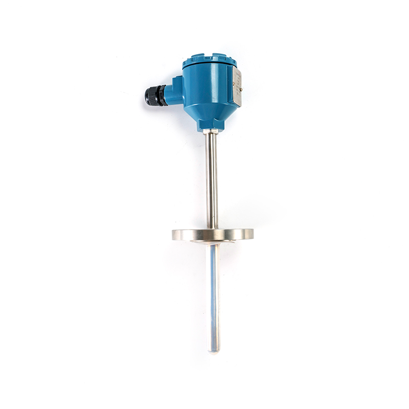
Assembly RTDThe sensing element is fitted into a removable assembly with a threaded or flanged connection. Easy to inspect and replace without replacing the thermowell.
|
Explosionproof RTDHoused in a flameproof enclosure approved for hazardous atmospheres. Prevents an internal ignition from propagating to the external gas or dust.
|
Anticorrosive RTDUses a chemically resistant sheath and sealing system for hydrochloric acid, sulfuric acid, or strong alkali exposure.
|
Abrasion-Resistant RTDFeatures a hardened tip and heavy-wall outer tube for pneumatic conveying, coal mills, and other high-wear processes.
|
The sheathed construction is the most common choice for a 4-wire RTD that has to be inserted into a pipeline or a machine casing with limited space. The mineral-insulated cable can be routed through a fitting, and the small diameter gives a short response time while maintaining electrical isolation between the element and the sheath. Xinguo Group offers a complete range of sheathed RTDs designed for permanent industrial installation, with options for custom lengths, terminal heads, and process fittings.
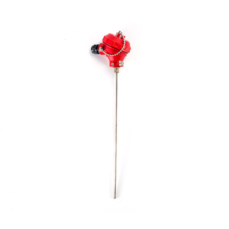 Compact Sheathed RTD with Fast Thermal Response for Tight SpacesThis sheathed RTD combines a stainless steel protection tube with magnesium oxide insulation for compact, vibration-resistant installation in pipelines or machine casings, delivering fast thermal response and electrical isolation with a long service life.View Product →
For applications that require periodic element replacement without shutting down the process line, an assembly RTD is usually the best fit. The thermowell stays installed in the pipeline, and the measuring insert can be withdrawn for inspection or exchange. The 4-wire assembly configuration is widely used in refining and petrochemical units because it allows convenient access to the element and simplifies maintenance.
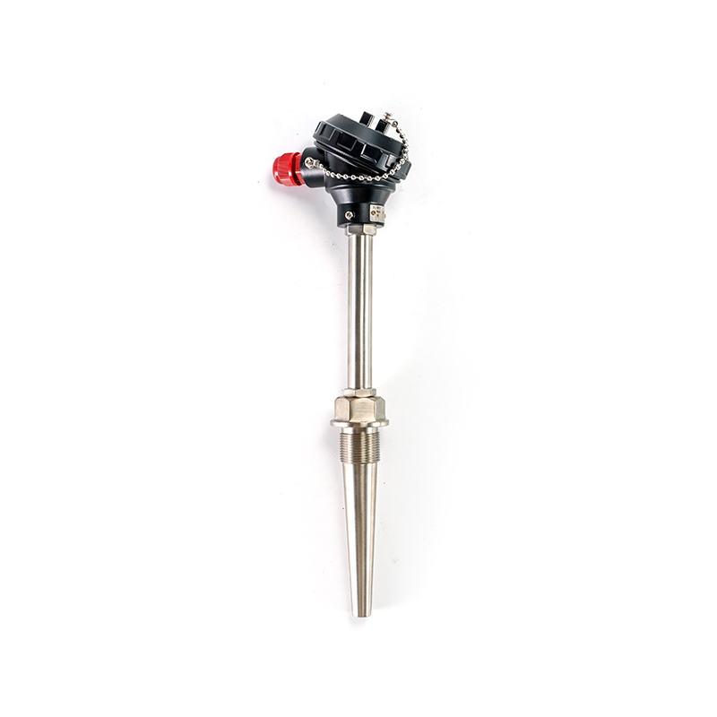 Assembly RTD with Removable Measuring Insert for Low-Maintenance ProcessesDesigned for direct temperature measurement in pipelines and tanks, this assembly RTD allows the sensing insert to be withdrawn for inspection or replacement while the thermowell remains installed, reducing process downtime in refining and petrochemical service.View Product →
Each probe style can be combined with different connection heads: a simple plastic head for dry indoor environments, an aluminum head for outdoor use, or a stainless steel head for corrosive and hygienic areas. The head can also house a smart transmitter that converts the RTD resistance into a standardized analog or digital output, reducing the number of conductors between the field sensor and the control room.
Selecting the correct 4-wire RTD is a matter of matching the measurement requirement with the process condition. The electrical specification defines the accuracy class and the nominal resistance, while the mechanical specification defines the sheath material, the connection thread, and the insertion length. The table below summarizes typical applications and the recommended probe style.
| Application area | Process condition | Recommended probe | Accuracy target |
|---|---|---|---|
| Power station boiler | High temperature, high pressure | RTD for power station, sheathed | Class A |
| Chemical reactor | Corrosive acids and alkalis | Anticorrosive RTD | Class A |
| Oil and gas production | Hazardous area Zone 1 / 2 | Explosionproof RTD | Class A or B |
| Cement mill, coal handling | Abrasive particles, vibration | Abrasion-resistant RTD | Class B |
| Pharmaceutical clean room | Sanitation, stable temperature | SS316L sheathed RTD | Class AA |
| Calibration laboratory | Controlled reference temperature | Glass or ceramic RTD | Class AA |
For hazardous areas, the explosionproof design encloses the electrical connections in a flameproof chamber. This is mandatory in many oil and gas, petrochemical, and paint storage environments. A 4-wire explosionproof RTD provides both the accuracy benefit and the necessary safety certification, allowing the temperature loop to be serviced without downgrading the area classification. Xinguo Group's explosionproof RTD range is engineered for Zone 1 and Zone 2 installations and is suitable for most demanding petrochemical projects.
 Explosion-Proof RTD for Hazardous Petrochemical SitesBuilt with a flameproof enclosure to house electrical connections, this RTD provides temperature measurement in explosive atmospheres without compromising precision, making it suitable for oil, gas, and petrochemical facilities where area classification must be maintained.View Product →
When comparing quotes for a new project, it helps to build a short specification that includes operating temperature range, process pressure, wetted material, thread size, insertion length, required accuracy class, and whether an Ex rating is required. A professional supplier can then match the 4-wire RTD construction to the actual service. In many cases, the same plant will need a mix of sheathed, assembly, and explosionproof probes, so it makes sense to work with a manufacturer that can supply the complete temperature instrument product range under one purchase order. For detailed evaluation of temperature measurement technology, the full catalogue published on the company website provides dimension drawings, wiring examples, and technical datasheets for every probe type.
Following this checklist eliminates most specification errors. A 4-wire RTD ordered with the correct process connection and insertion length can be installed with no modification, which reduces commissioning time and costs. For wholesalers, keeping a small stock of the most common sheath diameters and threads, such as 6 mm diameter with M20x1.5 thread, allows fast response to repeat orders from plant maintenance teams.
Price is often the deciding factor when a buyer chooses between a 3-wire and a 4-wire RTD. The difference in the sensor itself is small; most of the cost premium comes from the four-conductor cable, the terminal head, and the instrument channel. Nevertheless, the 4-wire version frequently creates net savings in the long run because it reduces commissioning faults, improves control stability, and extends the useful life of the measurement loop.
When the purchase decision involves a 4-wire RTD for a critical process, the buyer should review more than the price list. Verify that the manufacturer has in-house control over the entire production chain, from alloy wire to assembled probes. A producer that also manufactures thermocouple alloy wire and compensating extension wire, such as Xinguo Group, can often provide better material consistency, traceability, and faster custom design than a trading intermediary. Check the quality management system certificate, the availability of a calibration room, and the willingness to provide a material test report for the sheath and the element.
A manufacturer with a vertically integrated structure, meaning it controls the production of the alloy wire, the mineral-insulated cable, and the final sensor assembly, is usually more reliable for large projects. The internal transfer of materials follows the same quality control chain, and the buyer receives a single document set instead of a complicated chain of trading invoices. In practice, this also simplifies the audit process, because one factory visit covers the whole production line.
Wholesalers and distributors buying 4-wire RTD probes should define a minimum order quantity, packaging specification, and documentation package for export. Important export documents include commercial invoice, packing list, certificate of origin, and calibration reports in English. A reliable manufacturer will also mark each sensor with a serial number and store the calibration data for at least five years, making it easier for the wholesaler to handle customer claims and retracement.
For engineering teams in the process industry, establishing a framework agreement with a single supplier can reduce the number of variants by standardizing on a few documented 4-wire RTD configurations. This simplifies spare parts inventory, operator training, and future replacements. A standardisation programme might define one sheathed 4-wire RTD for general use, one assembly type for heat exchangers, and one explosionproof type for battery rooms and gas handling areas. With only three stock keeping units, the maintenance team can cover 80 percent of the plant's temperature points.
Shipping and packaging also deserve attention. 4-wire RTD probes are robust, but the platinum element can be damaged by severe mechanical shock. The manufacturer should ship the probes in individual corrugated tubes with protective end caps, and the calibration certificate should be placed in a sealed plastic bag inside the box. Wholesalers that re-export the sensors should request that the batch number and country of origin are printed on the outer carton to simplify customs clearance.
Even the most accurate sensor will not perform if the installation introduces thermal resistance, mechanical stress, or moisture. Follow the guidelines below to obtain the full benefit of a 4-wire RTD over its entire service life.
For plants that run continuous processes, keeping a spare 4-wire RTD in stock is a low-cost insurance against unplanned downtime. Always store the spare sensor in its original protective packaging with the calibration certificate kept dry and attached to the product label. When the spare is installed, the used sensor should be sent for calibration or inspection rather than thrown away, because the platinum element itself can often be re-certified several times before the sheath reaches its service limit.
A useful maintenance practice is to create a simple log for each temperature loop, recording the date of calibration, the measured resistance at 0°C and 100°C reference points, and any visual observations of the connection head. Over time, this log reveals drift trends that help predict the optimal replacement interval.
These are the questions that customers most often ask when choosing a 4-wire RTD for industrial measurement or wholesale purchase. The answers summarize the practical guidance discussed in this article and add a few extra details that help avoid procurement mistakes.
Why is a 4-wire RTD more accurate than a 3-wire RTD?A 3-wire RTD subtracts an estimated lead resistance based on one pair of matching wires. If the two wires have different resistance or are exposed to a temperature gradient, a residual error remains. A 4-wire RTD measures the element voltage through a separate pair of sense wires that carry no current, so lead resistance is removed completely, regardless of wire length or temperature. |
Can I connect a 4-wire RTD to a 2-wire transmitter?Physically yes, but you would lose the main benefit. If the transmitter only provides two terminals, the four sensor wires must be paired, and the lead resistance becomes part of the measurement again. To keep the accuracy advantage, use a transmitter or input module with a true 4-wire input mode. |
What is the difference between a Pt100 and a Pt1000 in a 4-wire circuit?Both can be made as 4-wire RTDs. A Pt100 has 100 ohms at 0°C and produces a moderate resistance change with temperature; a Pt1000 has 1000 ohms at 0°C, which gives a stronger signal per degree and lower self-heating. Pt1000 is often preferred for battery-powered or cable-limited systems, while Pt100 remains the industrial default. |
Does a 4-wire RTD require special extension wire?Unlike a thermocouple, an RTD does not need compensating cable. Standard copper stranded wire with adequate cross-section, typically 0.5 mm² or 0.75 mm², is sufficient. For long distances, twisted-pair signal wire with a shield is recommended to minimize induced noise on the sense circuit. |
How often should a 4-wire RTD be calibrated?For critical temperature loops, a calibration interval of six to twelve months is typical. The interval can be extended if the sensor is used in a temperate environment and the verification results remain well within tolerance over several consecutive cycles. |
What should I look for in a 4-wire RTD manufacturer?Look for ISO 9001 certification, a complete product range from alloy wire to finished probes, available calibration equipment, traceability documentation, and a willingness to produce custom lengths, sheaths, and process connections. A manufacturer that also produces thermocouple alloy wire and compensation cable often has stronger metallurgical supervision and a shorter supply chain, which benefits wholesalers and professional buyers. |
Can a 4-wire RTD be installed with only three wires?Technically the sensor can be connected in a 3-wire manner by combining one excitation wire and one sense wire on the same side of the element. Most transmitters will accept this as a 3-wire input. However, the measurement returns to a 3-wire compensation algorithm, so part of the lead resistance error comes back. This is sometimes done temporarily during commissioning, but it is not recommended for permanent critical loops. |
What causes self-heating in a 4-wire RTD and how can it be reduced?Self-heating occurs when the excitation current dissipates power in the platinum element, raising its temperature above the process temperature. Using a lower excitation current, for example 0.5 mA instead of 1 mA, reduces self-heating by a factor of four. A Pt1000 element also runs cooler than a Pt100 at the same current because its higher resistance dissipates the same power over a smaller current requirement. |
For engineering and purchasing teams that need further product information, the links below provide direct access to the full catalogue and the sales engineering support desk. A complete specification package can be prepared from the product pages, or a custom quotation can be requested directly from the manufacturer.
Working with a supplier that understands both the measurement technology and the practical installation requirements makes it easier to specify, commission, and maintain temperature loops that perform as designed. A 4-wire RTD is a small component, but it is the starting point for trustworthy plant data, and therefore the starting point of a reliable control system.



 INQUIRY
 English
 عربى
عربى русский
 中文简体
中文简体