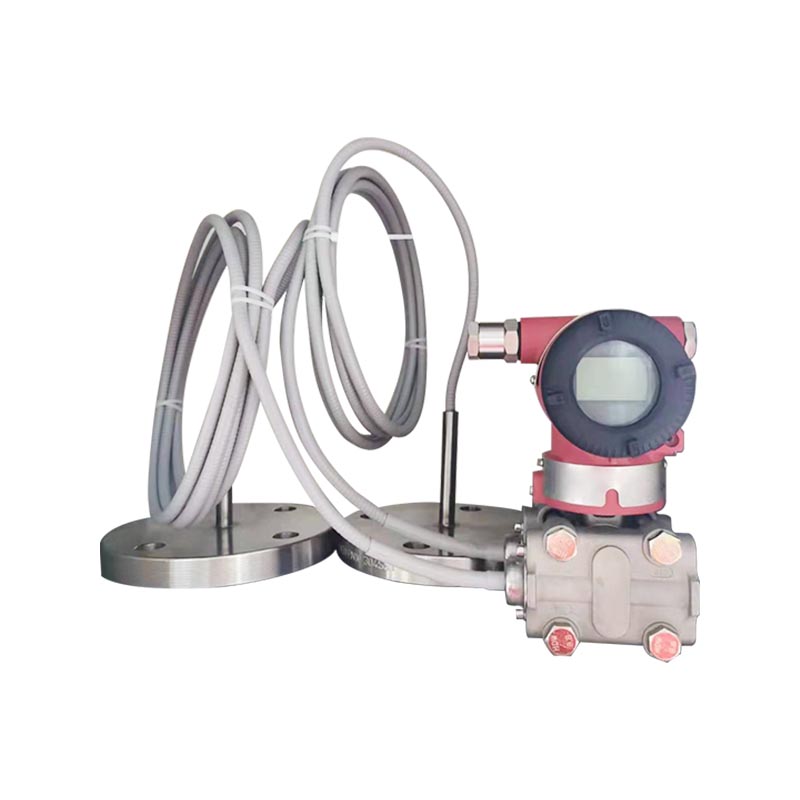
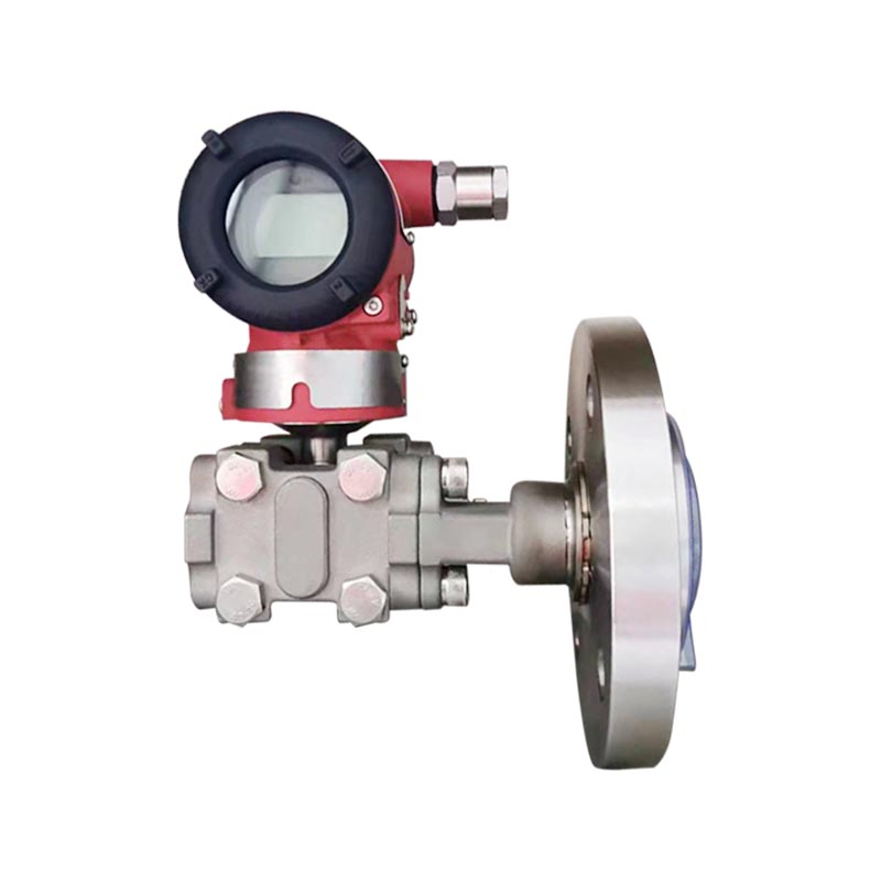
XG3051DP Differential pressure remote transmitter Manufacturers
Home / Product / Pressure instruments / pressure transmitter / XG3051DP Differential pressure remote transmitter
  • XG3051DP Differential pressure remote transmitter
  • XG3051DP Differential pressure remote transmitter

XG3051DP Differential pressure remote transmitter

Product Introduction:
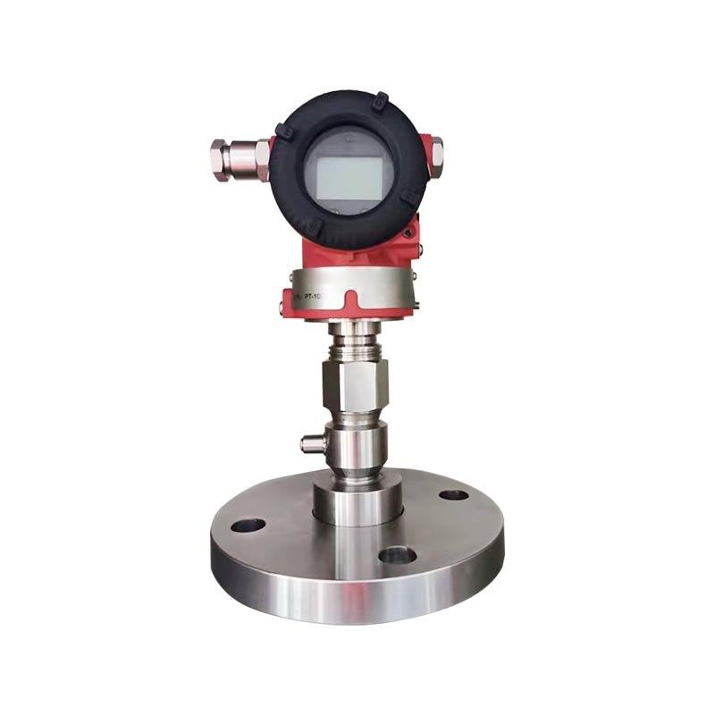
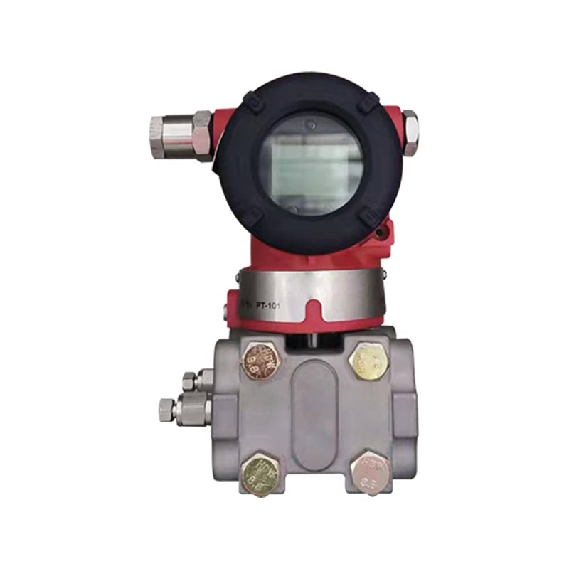
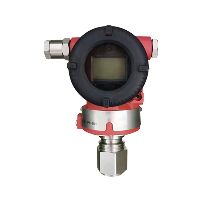
XG3051DP intelligent remote differential pressure transmitter, dual-flange capillary remote transmission structure, measures medium differential pressure, and can achieve liquid level, flow rate, density, and differential pressure measurement; isolates the measured medium from the sensor body, adapts to high viscosity, easy crystallization, easy solidification, high temperature, strong corrosive media, and prevents blockage and corrosion of the measurement membrane box.
Two wire 4-20mA+HART protocol output, supporting on-site configuration of HART controller and header buttons, range migration, adjustable damping, high accuracy, and good long-term stability; Optional LCD with explosion-proof protection. The membrane can be made of materials such as 316L, Hastelloy, tantalum, etc. It can be connected to PLC/DCS systems and is commonly used for measuring the liquid level and flow rate of closed tanks, reaction vessels, and throttling devices.

Applicable industries:
Petrochemical industry: reaction kettle, storage tank liquid level, flow detection
Coal chemical industry: monitoring of liquid level differential pressure in various process tanks and towers
Electricity: boiler, thermal system differential pressure, liquid level measurement
Metallurgy: Testing of smelting process tanks and sealed containers
Pharmaceutical: Measurement of liquid level in closed reaction tanks and fermentation tanks
Food and beverage: viscous materials, liquid level in sealed tanks
Water treatment: chemical wastewater tank, closed container liquid level
Paper making: differential pressure of liquid level in pulp and viscous medium tanks

Core Advantage Specification Application Feature FAQ Instructions

General Conditions
The transmitter body can be fixed at any position. The optimal installation condition is to keep the process flange shaft vertical. Position deviation will cause a correctable zero shift. The electronic housing can be rotated up to 360°, and the set screw can secure it at any angular position.
The remote seal flange connects to a mating flange complying with ANSI/DIN standards. The mating flange shall be equipped with a soft gasket and mounting bolts and nuts (bolts and nuts are optional for users).
For dual remote seal transmitters, the capillary assemblies and remote seal flanges shall be installed in an environment with the same ambient temperature as far as possible.
The minimum bending radius of the capillary is 75 mm. Coiling is strictly prohibited!

Environmental conditions

Ambient Temperature
Minimum Depends on fill fluid
Maximum 85 ℃
With LCD and FKM seal -20 ~ 65 ℃
Storage / Transport Temperature
Minimum Depends on fill fluid
Maximum 85 ℃
Relative Humidity 0 ~ 100 %
Shock Resistance
Acceleration 50 g
Duration 11 ms
Vibration Resistance 2 g up to 500 Hz
Electromagnetic Compatibility (EMC) See Table 4 "EMC Appendix" on the next page

Process medium limit temperature limit
Medium temperature:-30~400°C

Table 3 Relationship of Fill Fluid, Operating Temperature and Minimum Operating Pressure
Fill Fluid Silicone Oil (S) High-Temp Silicone Oil (H) Ultra-High-Temp Silicone Oil (U) Vegetable Oil (V)
Density @25℃ 960 kg/m³ 980 kg/m³ 1020 kg/m³ 937 kg/m³
Operating Temperature Range -30 ~ 200℃ -10 ~ 350℃ -10 ~ 400℃ 0 ~ 250℃
Temperature Operating Pressure Range (kPa absolute)
20℃ >10 >10 >10 >25
100℃ >25 >25 >25 >50
150℃ >50 >50 >50 >75
200℃ >75 >75 >75 >100
250℃ >100 >100 >100
350℃ >100 >100
400℃ >100

Note: Special attention should be paid to any values exceeding the above temperature and pressure range; these can be met through
special design.

Item Description
Transmitter Body Pressure Limit From 3.5 kPa absolute pressure to rated pressure. The protection pressure can be 1.5 times greater than the rated pressure, applied to both sides of the transmitter simultaneously.
Remote Flange Rated Pressure ANSI standard: 150psi ~ 600psi
DIN standard: PN 1.6MPa ~ PN 10MPa
Unidirectional Overload Limit The low-pressure side is the rated pressure of the transmitter body; the high-pressure side is the rated pressure of the remote flange. A correctable zero drift may occur.
Weight Single-sided remote:
DN 50/2": approx. 7 ~ 10 kg
DN 80/3": approx. 8 ~ 11 kg
DN 4": approx. 9 ~ 12 kg
Double-sided remote:
DN 50/2": approx. 10 ~ 16.5 kg
DN 80/3": approx. 12 ~ 18 kg
DN 4": approx. 14 ~ 21 kg
Explosion-proof Performance NEPSI Flameproof Certificate: Ex dⅡC T6
NEPSI Intrinsically Safe Certificate: Ex iaⅡC T4
Permissible operating temperature -40℃ ~ 65℃

Power and Load Conditions
Power supply voltage is 24V
R≤(Us-12V) /Imax kQ 2
where Imax=23 mA
Maximum power supply voltage: 42VDC
Minimum power supply voltage:12VDC,15VDC(backlight LCD display)
Digital communication load range: 250~600Q

Item Description
Material
Measuring Capsule Stainless Steel 316L
Diaphragm Stainless Steel 316L, Hastelloy C, Tantalum
Process Flange Stainless Steel 304
Fill Fluid Silicone Oil, High-Temp Silicone Oil, Ultra-High-Temp Silicone Oil, Vegetable Oil
Sealing Ring NBR (Nitrile Butadiene Rubber), FKM (Fluoro Rubber), PTFE (Polytetrafluoroethylene)
Transmitter Housing Aluminum Alloy, surface spray-coated with Epoxy Resin
Housing Gasket NBR (Nitrile Butadiene Rubber)
Nameplate Stainless Steel 304
Electrical Connection M20×1.5 cable gland; terminals suitable for 0.5 ~ 2.5 mm² conductors
Process Connection NPT 1/4 and UNF 7/16" internal threads on the low-pressure side of the transmitter. The level flange on the high-pressure side complies with ANSI or DIN standards. Direct mounting available; refer to Page 42, Part 7.
Housing Protection Class IP67

Table 4 Electromagnetic Compatibility
No. Test Item Basic Standard Test Condition Performance Level
1 Radiated Disturbance (Enclosure) GB/T 9254-2008 Table 5 30MHz ~ 1000MHz Pass
2 Conducted Disturbance (DC Power Port) GB/T 9254-2008 Table 1 0.15MHz ~ 30MHz Pass
3 Electrostatic Discharge (ESD) Immunity GB/T 17626.2-2006 4kV (Contact) B
8kV (Air)
4 Radio-Frequency Electromagnetic Field Immunity GB/T 17626.3-2006 10V/m (80MHz ~ 1GHz) A
5 Power Frequency Magnetic Field Immunity GB/T 17626.8-2006 30A/m A
6 Electrical Fast Transient / Burst Immunity GB/T 17626.4-2008 2kV (5/50ns, 5kHz) B
7 Surge Immunity GB/T 17626.5-2008 1kV (Line-to-Line) B
2kV (Line-to-Ground) (1.2us/50us)
8 Conducted Disturbance Immunity Induced by Radio-Frequency Fields GB/T 17626.6-2008 3V (150kHz ~ 80MHz) A

Note: (1) A Performance Level Description: During testing, performance is normal within the technical specification limits.
(2) B Performance Level Description: During testing, functions or performance temporarily decrease or disappear but can recover on their own; actual operating conditions, storage, and data remain unchanged.

Input

Measurement Parameters: Differential Pressure, Liquid Level

Measurement Range
Lower Limit From -100% URL (continuously adjustable)
Upper Limit Up to +100% URL (continuously adjustable)
Table 1 — Relationship between Range Code and Range
Range Code Minimum Range Maximum Range Rated Pressure (Max)
B 1 kPa 6 kPa Rated pressure of the remote flange
C 4 kPa 40 kPa Rated pressure of the remote flange
D 25 kPa 250 kPa Rated pressure of the remote flange
E 200 kPa 2 MPa Rated pressure of the remote flange
Table 2 Remote Seal Flange vs Minimum Range
Level Flange Type Nominal Diameter Minimum Range
Single Remote Seal Dual Remote Seal
Flat Type DN 50 / 2" 10 kPa 10 kPa
Flat Type DN 80 / 3" 6 kPa 1 kPa
Flat Type DN 4" 6 kPa 1 kPa
Inserted Type DN 50 / 2" 16 kPa 16 kPa
Inserted Type DN 80 / 2" 6 kPa 1 kPa
Inserted Type DN 4" 6 kPa 1 kPa

The minimum range of the remote transmitter should be the larger value between the minimum ranges in Table 1 and Table 2.
The adjustable range shall not be less than the minimum range. The maximum range of the remote transmitter shall be the smaller value between the maximum range of the transmitter body and the rated pressure of the level flange.

Output

Output Signal
2-wire, 4–20 mA DC HART output, digital communication; the HART protocol is superimposed on the 4–20 mA DC signal.
Output Signal Limits: Imin = 3.9 mA, Imax = 20.5 mA

Alarm Current (Configurable Mode)
Low Alarm Mode (Minimum) 3.7 mA
High Alarm Mode (Maximum) 21 mA
No Alarm Mode (Hold) Holds the valid current value before a fault
Standard Setting of Alarm Current High Alarm Mode


Response Time
The damping constant of the amplifier component is 0.1 s; the time constant of the sensor and remote seal flange ranges from 0.2 ~ 6 s, depending on the sensor range, range ratio, capillary length, and viscosity of the fill fluid.
The additional adjustable time constant ranges from 0.1 ~ 60 s.

Q1: What is the main purpose of the XG3051DP dual-flange remote transmitter for measuring?
A: Mainly used for measuring differential pressure; often used for measuring liquid level, flow rate, and medium density in closed tanks. Double flange capillary isolation structure, suitable for high viscosity, easy crystallization, strong corrosion, and high temperature media, to avoid medium blockage and corrosion of the sensor body, output 4-20mA+HART, and interface with DCS/PLC system.
Q2: What are the reasons for inaccurate zero point and numerical drift after double flange installation?
A: Drift can be caused by environmental temperature changes, capillary compression, membrane scaling and crystallization, and incorrect migration parameter settings. After installation, on-site zero point migration must be carried out; Avoid squeezing and small-radius bending of capillaries; When the operating temperature changes significantly, increase the instrument damping appropriately.
Q3: How to choose the material of flange diaphragm?
A: 316L stainless steel is selected for normal working conditions; Corrosive media can be selected from Hastelloy alloy and tantalum film. When placing an order, provide the medium name, temperature, and pressure for easy matching of diaphragm and capillary filling fluid.
Q4: What are the taboos for installing capillary tubes?
A: Cutting or hard bending of capillary tubes is not allowed; the minimum bending radius is> 50 mm, and they cannot be squeezed or bumped. The capillary tube is filled with sealing liquid inside. Once it is damaged and leaks, the instrument will directly fail and cannot be repaired on site.

Dimensions

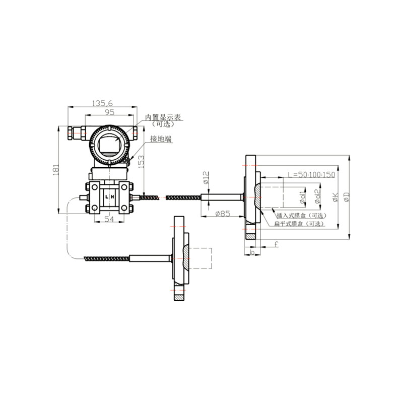
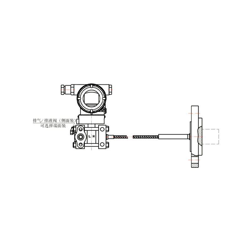
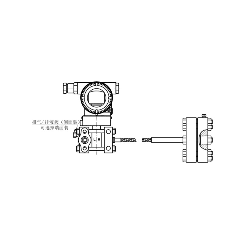
Drawing 1: Basic Type Double-sided Differential Pressure Remote Seal Assembly Drawing Drawing 2: Basic Type Single-sided Differential Pressure Remote Seal Assembly Drawing
100061 100052

Note:
(1) The single-sided basic type differential pressure remote seal assembly can be installed on either the high-pressure side or the low-pressure side of the transmitter body.
(2) The installation method of the transmitter body for single-sided or double-sided basic-type differential pressure remote seal assemblies is the same as that of the XG3051DP series differential pressure transmitter.

Table 5 Remote Flange Structural Dimension Table
Nominal Diameter Rated Pressure ΦD ΦK Φd1 Φd2 Φd3 t b Bolts Required
Insert Type Flat Type Quantity Thread
DN 50 (Sealing face DIN 2526 Type E)(Flange DIN 2501) PN1.6/4MPa 165 125 48.3 57 102 3⁺⁰·⁵ 20 4 M16
PN6.4MPa 185 135 48.3 57 102 3⁺⁰·⁵ 26 4 M20
PN10MPa 195 145 48.3 57 102 3⁺⁰·⁵ 28 4 M20
DN 80 (Sealing face DIN 2526 Type E)(Flange DIN 2501) PN1.6/4MPa 200 160 76 75 138 3⁺⁰·⁵ 24 8 M16
PN6.4MPa 215 170 76 75 138 3⁺⁰·⁵ 28 8 M20
PN10MPa 230 180 76 75 138 3⁺⁰·⁵ 32 8 M24
DN 2" (ANSI B 16.5 RF Type) 150psi 152.4 120.6 48.3 57 92.1 3⁺⁰·⁵ 17.4 4 M18
300psi 165.1 127 48.3 57 92.1 3⁺⁰·⁵ 20.6 8 M18
600psi 165.1 127 48.3 57 92.1 6.35 31.75 8 M18
DN 3" (ANSI B 16.5 RF Type) 150psi 190.5 152.4 76 75 127 3⁺⁰·⁵ 22.2 4 M16
300psi 209.5 168.3 76 75 127 3⁺⁰·⁵ 27 8 M20
600psi 209.5 168.3 76 75 127 6.35 38.05 8 M20
DN 4" (ANSI B 16.5 RF Type) 150psi 229 191 89 89 157 3⁺⁰·⁵ 30 8 M18
300psi 255 200 89 89 157 3⁺⁰·⁵ 32 8 M18

Note:Usercanoptionallyequipinsaatonbosannut.

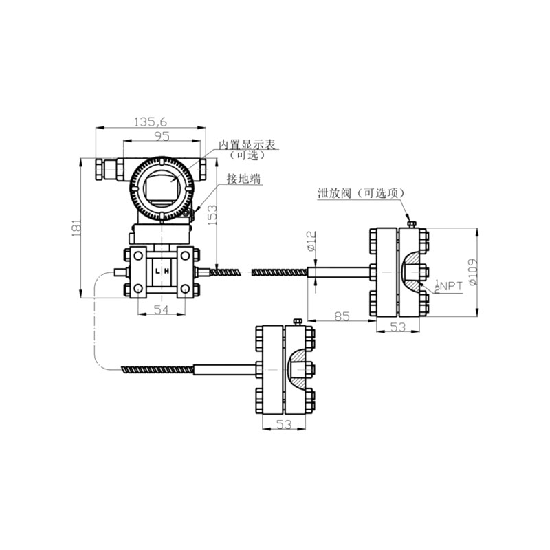
Figure 3 Figure 4 Single-sided Thread-mounted Differential Pressure Remote Seal Assembly
100043 100034

Note:
(1) The single-sided thread-mounted differential pressure remote seal assembly can be installed on either the high-pressure side or the low-pressure side of the transmitter body.
(2) The installation method of the transmitter body for single-sided and double-sided thread-mounted differential pressure remote seal assemblies is the same as that of the XG3051DP series differential pressure transmitter.

Xinguo Group Co., Ltd.
ABOUT US Xinguo Group Co., Ltd.
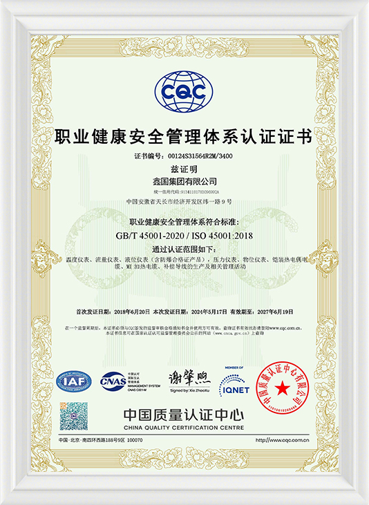
Xinguo Group Co., Ltd. is a high-tech enterprise with subsidiaries including Anhui Xinguo Instrument Co., Ltd., Anhui Xinguo Alloy Co., Ltd., Anhui Xinguo Cable Co., Ltd. and Anhui Xinguo Precious Metals Co., Ltd. Founded in 1997, the Group is located in Tianchang City, Anhui Province — a National Civilized City. It has a registered capital of 118 million RMB, covers a land area of over 150 mu and a building area of 60,000 square meters. The company currently has more than 300 employees, among whom over 50 are professional and technical personnel including senior engineers, engineers and assistant engineers.
The Group is a China Custom XG3051DP Differential pressure remote transmitter Manufacturers and XG3051DP Differential pressure remote transmitter Supplier, mainly engages in the R&D, production and sales of temperature instruments, pressure instruments, level instruments, flow instruments and digital display instruments. Its product portfolio also encompasses power cables, control cables, compensation cables, computer cables, signal cables, MI heating cables, mineral insulated cables, electric heat tracing tapes, cable trays and accessories, high and low voltage distribution equipment, complete automation control systems, instrument valves, pipeline valves and fittings, glass instruments and laboratory equipment. We also supply platinum-rhodium wires, precision alloys and complete mechanical equipment, while providing supporting processing, manufacturing, sales and technical services. Additionally, we deal in professional instrument materials, alloy materials and precious metals. Our products are widely applied in power, petroleum, chemical, metallurgy, building materials, machinery, food, aerospace, new energy and other industrial sectors, as well as scientific research and education fields.
Anhui Xinguo Alloy Co., Ltd. is dedicated to manufacturing a full range of precision alloy materials and serves as a council member of the Instrument Materials Branch of China Instrument & Control Society. Its flagship products cover thermocouple alloy wires (K, N, E, J, T types), thermocouple compensation alloy wires (KX, EX, NX, JX, TX, KCA, KCB, NC, SC), high-resistance heating alloys, precision resistance alloys, heating resistance alloys, pure nickel wires, manganese-copper alloys and Monel alloys. These products are extensively used in aviation, petroleum, chemical engineering, machinery manufacturing, power and energy industries.

  • 0year

    Founded in

  • 0+mu

    Cover an area of

  • 0+

    Experienced employees

  • 0

    Building area

NEWS Provide You With The
Latest Enterprise and Industry News