A kiln shell glowing at 950 °C, a plastic film running at 200 metres per minute, a molten aluminium stream behind a heat shield, a roller bearing buried inside a sealed gearbox. None of these targets will accept a probe, and none of them care whether your instrument has a nice certificate. An infrared sensor reads the radiant energy these surfaces emit and converts it into a temperature value without ever touching the target. That single property decides where the technology wins, and where it quietly misleads the people reading the trend screen.
Here is the short answer before the detail. Choose an infrared sensor when the target moves, rotates, sits behind glass or a screen, has to stay hygienic, or is simply too hot, too small or too far away for a contact probe to survive. Choose a contact sensor, meaning a resistance thermometer or a thermocouple, when the target is stationary, when nobody on site can confirm the surface emissivity, or when the process demands uncertainty tighter than a fraction of a degree. Most plants that get temperature right run both technologies side by side, and the contact sensors that keep the infrared reading honest are built from alloy wire that has to hold its electromotive force for years.
Xinguo Group Co., Ltd., founded in 1997 in Tianchang, Anhui Province, works on both sides of that line. The group combines alloy material production, thermocouple alloy wire, thermocouple compensating wire, resistance thermometer manufacturing, instrument materials, cable and precious metal operations under one organisation, with roughly 300 employees, more than 50 of them technical staff including senior engineers and engineering specialists. The group states that it operates ISO9001:2008, ISO14001:2004 and GB/T28001:2001 management systems. That combination matters in this discussion because an infrared sensor is only as good as the reference used to verify it, and the reference is almost always a contact sensor made from controlled alloy materials.
Rule of thumb: pick an infrared sensor for speed, access and safety, pick a contact RTD or thermocouple for accuracy, and use both whenever the numbers have to survive an audit.
Every object above absolute zero radiates electromagnetic energy, and the amount it radiates rises steeply with temperature. Roughly speaking, the radiated power is proportional to the fourth power of absolute temperature, which is why a surface at 900 °C radiates thousands of times more energy than the same surface at 25 °C. An infrared sensor does three things: its optics collect part of that radiation, a detector converts it into an electrical signal, and the electronics convert that signal into a temperature using a stored emissivity value and a calibration curve.
The detector itself may be a thermopile, a pyroelectric element, a photodiode or a bolometer, and the choice of detector usually follows the wavelength band. Short wavelengths around 1.0 µm or 1.6 µm suit very hot targets such as molten metals, where the signal is strong and the surrounding ambient temperature contributes little. A 3.9 µm band helps when the sight path crosses a flame or a combustion zone. A 5.0 µm band is common for glass surfaces, since the glass itself is largely opaque there. The familiar 8 to 14 µm band covers the widest range of general industrial surfaces at moderate temperatures and is the band most often chosen for food, paper, plastics and electrical equipment.
Four parameters account for most of the difference between a reading you can trust and a reading that drifts by twenty degrees after installation.
Emissivity deserves its own reference table, because it is the parameter most often guessed. The values below are typical starting points for setup; the true value on your line depends on oxidation, surface roughness, contamination and temperature.
| Surface | Typical emissivity | Practical note |
|---|---|---|
| Polished aluminium, bright | 0.05 to 0.12 | Reads far too low with a general-purpose band; use a short-wavelength sensor or change the sight path |
| Oxidised or anodised aluminium | 0.25 to 0.45 | Stable enough for trend monitoring, still needs verification |
| Rolled or rough steel | 0.70 to 0.90 | Common in kiln shells, furnace casings and strip lines |
| Oxidised stainless steel | 0.50 to 0.85 | Scattered data; measure a sample in the plant |
| Painted or coated surfaces | 0.90 to 0.96 | Nearly independent of the metal underneath |
| Plastic film and sheet | 0.90 to 0.95 | Band choice matters more than the emissivity setting |
| Glass, softened surface | 0.85 to 0.95 in the 5 µm band | Long-wavelength sensors see through thin glass rather than into it |
| Paper, cardboard, wood | 0.85 to 0.95 | Straightforward general-purpose application |
| Rubber, asphalt, dark plastics | 0.90 to 0.98 | Close to blackbody behaviour |
| Calibrator cavity reference | 0.99 or above | Used when verifying the sensor against a known source |
A useful sanity check when emissivity is uncertain: paint a small patch of the surface with a matte coating of known, high emissivity, let it reach process temperature, and compare a reading on the patch with a reading on the bare surface. If the two disagree by more than a couple of degrees, the emissivity setting for the bare surface is wrong, not the sensor.
Most infrared temperature errors in industry are emissivity errors, not hardware errors, which is why the first verification step is always a contact reference measurement on the same surface.
Engineers rarely choose between these three instruments in the abstract. They choose based on what the target allows, how tight the tolerance is, and how much maintenance the measurement point can absorb. The table below compares them for a stationary target in the 300 °C region, which is a fair middle ground for industrial work.
| Consideration | Infrared sensor | RTD (resistance thermometer) | Thermocouple |
|---|---|---|---|
| Measurement principle | Radiated energy, non-contact | Resistance change in a metal element | Thermoelectric voltage at a junction |
| Typical accuracy near 300 °C | Several degrees, dominated by emissivity and spot size | Fractions of a degree for a calibrated Class A or Class AA element | A few degrees for a standard tolerance junction |
| Response to a step change | Often milliseconds | Seconds in a sheath, longer in a thermowell | Sub-second for an exposed junction |
| Moving or rotating target | Directly supported | Requires a slip ring or wireless transmitter | Requires the same workaround |
| Low-emissivity or polished metal | Difficult and error-prone | Straightforward once contact is made | Straightforward once contact is made |
| Contamination and hygiene risk | None, target untouched | Requires an intrusive connection | Requires an intrusive connection |
| Typical maintenance drivers | Lens cleanliness, emissivity verification, calibration | Drift in the element, lead resistance, sheath corrosion | Junction oxidation, wire contamination, ageing |
| Best fit | Hot, moving, sealed or hygienic targets | Stable processes needing the tightest accuracy | Wide temperature span, fast response, rugged installation |
The pattern behind the table is simple. Contact sensors measure the temperature of the sensor itself and hope the sensor has reached the temperature of the process. Infrared sensors measure the surface directly and hope the surface behaves the way the emissivity setting claims. Both are assumptions. The difference is that the contact assumption is usually easier to verify with a second instrument, while the emissivity assumption requires knowing something about the material.
There is a third practical point that rarely appears in datasheets: the total cost of ownership curve looks different for the two families. An infrared sensor avoids thermowells, isolation fittings, welded bosses and process shutdowns, which can dominate the installed cost on an existing line. A contact sensor avoids re-verification of emissivity every time the surface condition changes, which can dominate the maintenance cost over a ten-year life. Neither advantage is universal.
An infrared sensor usually wins on access and speed, a contact RTD usually wins on accuracy, and the deciding factor is which of those two the process can least afford to lose.
The applications below are the ones that come up repeatedly in industrial practice, and they share a common trait: the target will not tolerate contact, or the contact sensor will not survive.
There are also three situations where an infrared sensor will underperform, and recognising them early saves weeks of troubleshooting.
A bright, low-emissivity surface reflects the surroundings as strongly as it emits. If a cold wall or a warm furnace roof is reflected into the sensor's field of view, the reading follows the reflection, not the metal. Painting a patch, roughening the surface, or using a short-wavelength sensor with a verified emissivity helps; simply turning up the emissivity setting until the number looks right does not.
Steam, flour dust, cement dust, oil mist and airborne fibres all absorb and scatter infrared energy. A sensor commissioned on a clean line can lose twenty degrees of apparent temperature after three months of dust build-up on the lens. Air purge and a scheduled cleaning routine are part of the installation, not optional extras.
If a 4 mm wire or a 6 mm bearing race sits inside a 40 mm measurement spot, the instrument reports an average of wire and background. The reading moves with ambient temperature rather than with the process, which is exactly the behaviour that makes operators distrust infrared measurement altogether.
Before any infrared sensor is ordered, confirm three things: the surface emissivity, the smallest target that must be filled by the spot, and what will be sitting in the sight path after six months of production.
An infrared sensor is the visible half of a temperature measurement chain. The invisible half is the reference chain: the contact sensor used to verify the infrared reading, the calibrator cavity that provides a known source, and the wire that carries the millivolt signal from that reference sensor to the transmitter. Alloy consistency in that chain determines whether the verification means anything.
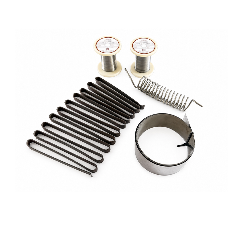
Thermocouple alloy wire is the foundation. Type K wire, with its nickel-chromium and nickel-aluminium pair, remains the workhorse for general industrial reference work. Type N offers better stability at high temperature. Type E delivers the highest sensitivity among the common base-metal pairs. Type T suits the low-temperature end of the range, including food and refrigeration verification. Type J covers older installations. Each pair has a nominal electromotive force curve, and each has a tolerance band that decides how much of your uncertainty budget the reference itself consumes.
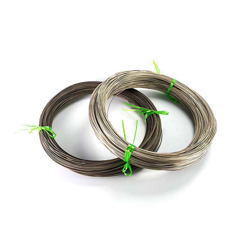 Thermocouple alloy wireProduct Introduction Thermocouple alloy wire is a precision temperature‑measuring alloy wire mainly composed of nickel, chromium, silicon, copper and other metals. Con...View Product →
What matters to a buyer is not the chemistry description but the repeatability from spool to spool. A reference thermocouple built from a wire batch that sits at the edge of the tolerance band will move the whole calibration chain. Composition control, drawing practice, surface condition and annealing all influence how the wire behaves after it has been bent, welded and cycled a few hundred times. Suppliers who draw and anneal their own alloy wire can usually answer questions about batch traceability that a trading company cannot.
The thermocouple voltage is generated between the junction and the cold junction at the transmitter terminals. If ordinary copper cable runs that distance, a second, unwanted thermocouple forms at the terminals, and the error grows with the temperature difference between the two ends. Compensating wire is manufactured to follow the thermocouple's voltage curve over a limited temperature range, so the signal arriving at the transmitter represents the process, not the cable route.
Practical selection points for compensating wire include the insulation class, since a cable routed near a furnace needs a different jacket from one running inside a control cabinet; the conductor cross-section, which affects loop resistance; and the shielding arrangement, which decides how much electrical noise reaches a sensitive input. Colour codes and polarity conventions vary between standards, so a mismatched connection is a common cause of a reading that is consistently wrong by a fixed offset.
Manganin alloy wire is used where stable resistance is required, including precision resistors and shunt elements in measurement circuits. Constantan wire appears both in thermocouple pairs and in low-resistance applications. Pure nickel wire suits specific resistance and electrode duties. Monel nickel-copper alloy wire brings corrosion resistance to hostile environments. Nichrome and nichrome-iron wire serve heating duties, where the wire itself becomes the heat source. A plant that measures temperature and also heats, stirs or melts product often needs two or three of these families from the same supplier.
The practical benefit of sourcing alloy materials and finished instruments from one manufacturing group is that the interface between them, which is the wire inside the RTD, the junction inside the thermocouple and the terminal block inside the transmitter, lands inside one quality system instead of two. Xinguo Group's structure, which brings alloy material, cable and instrument operations together, is designed around that overlap.
When you verify an infrared sensor, you are trusting the reference thermocouple more than the infrared device, so the tolerance and traceability of the alloy wire in that reference is part of the measurement spec.
Specification is where most projects either become simple or become expensive. Working through the following sequence takes about an hour and prevents the four most common returns.
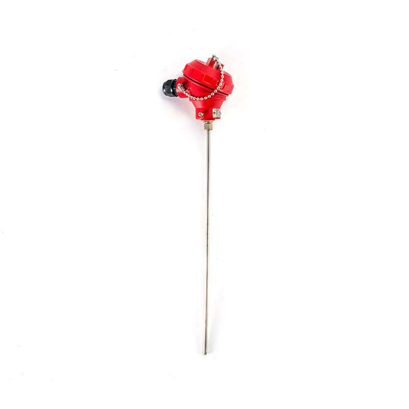 Sheathed RTDComposed of a stainless steel protection tube, Magnesium Oxide insulating powder, thermocouple wire combination, the overall by solid die compaction, with pressure, se...View Product →
Step nine is the one most often skipped, and it is the one that repays the effort. A sheathed resistance thermometer, with a bendable stainless sheath and a small tip, can be used to touch a verification patch on a moving web, a stationary sample of the product, or a test block bolted to the same surface. Because the sheath can be routed into awkward positions, it reaches places a rigid assembly cannot. Comparing its reading with the infrared reading at the same instant gives a direct indication of whether the emissivity setting is reasonable.
Where the process cannot be interrupted for verification, a removable test target with a known high emissivity, mounted adjacent to the measured surface, gives the same information without touching the product. This approach works well on kiln shells, strip lines and roller surfaces.
Specify the distance-to-spot ratio and the verification method before you compare sensor prices, because those two decisions determine whether the cheaper unit will ever produce a usable number.
Mounting decisions made in an afternoon can undermine an instrument worth several thousand dollars, and they are difficult to undo once cable trays and brackets are in place. The following practices come from the kinds of problems that show up during commissioning rather than from laboratory conditions.
Mount the sensor perpendicular to the target surface wherever the mechanical layout allows. Angles beyond about 30 degrees from normal increase the effective spot size, change the apparent emissivity and add a reflection path from surrounding equipment. On cylindrical targets such as kiln shells or rollers, mount on the surface normal at that point rather than on the tangent, and check that the sensor cannot see itself reflected in the metal.
Air purge performs two jobs: it keeps the lens cooler and it keeps dust, steam and fumes out of the optical path. Dry, oil-free instrument air is the usual choice, with the purge flow set at the manufacturer's recommendation rather than at the maximum the regulator can deliver. Where the process atmosphere is corrosive or the housing must be sealed, a protective window in a material that transmits the chosen band is fitted and cleaned on a schedule. A dirty window that is treated as a permanent fixture can shift a reading by more than any calibration adjustment.
Route sensor cable away from variable-frequency drive output cables, welding leads and heavy power feeders. Use shielded cable with the shield terminated at one end, follow the manufacturer's grounding scheme, and keep the signal and power conductors in separate bundles. On a mill floor, the difference between a stable reading and a noisy one is often nothing more than thirty centimetres of cable separation.
Commission with a comparison measurement, not with a guess. Record the ambient temperature at the mounting point, the emissivity value entered, the spot size at the working distance, and the reading obtained on a reference surface. Repeat the comparison after the first production week, when the line has reached real operating conditions and any condensation or dust loading has appeared.
Perpendicular mounting, a clean optical path and a documented baseline comparison will prevent more infrared measurement problems than any change to the electronics.
Infrared sensors drift, but they rarely drift in the way that operators imagine. The detector and electronics are usually stable. What changes over time is the optical path, the surface condition and the ambient environment. A calibration schedule that only checks the electronics misses two thirds of the problem.
Blackbody calibration is the classical approach. The sensor is aimed at a cavity source held at a known temperature, and the indicated value is compared with the source value. Cavities with emissivity around 0.99 reduce the uncertainty contributed by the source itself. This method establishes the sensor's response against a defined radiator.
Comparison calibration is the practical alternative on site. A contact reference sensor, typically a calibrated resistance thermometer or a thermocouple built from certified alloy wire, is placed on or in a stable target, and the infrared reading is compared with the reference. The advantage is that the measurement happens on the real material with the real surface condition, so the emissivity setting is validated rather than assumed. The disadvantage is that the reference itself introduces uncertainty, which is why the reference should be a grade or two better than the accuracy you expect from the infrared sensor.
An uncertainty budget for an installed infrared sensor usually contains contributions from the calibration source, the emissivity setting, the target spot fill, the ambient temperature at the housing, the transmission of any protective window, and the electronics repeatability. In practice, emissivity and spot fill dominate, and improving them produces a larger gain than replacing the sensor with a higher-specification model.
A reasonable interval for most industrial installations is a verification every six to twelve months, tightened to quarterly where the process runs near a quality limit or where the surface condition changes with the product mix. Any verification should be recorded with the conditions at the time, including ambient temperature and cleaning status, so a later comparison means something.
Calibrate the sensor against a known radiator, but validate the whole measurement against a contact reference on the real surface, because that is where emissivity and spot fill actually get tested.
Buyers often compare an infrared sensor and a contact sensor on the datasheet accuracy figure alone, which is misleading. The figure that governs plant performance is the total uncertainty at the measurement point, and that includes the installation and the surface. The chart below illustrates typical orders of magnitude for a stationary 300 °C surface, on the understanding that real numbers must be established per application.
Typical total measurement uncertainty near 300 °C, by method and setup
Values indicate typical magnitudes for comparison only. Actual uncertainty depends on calibration grade, installation, surface condition and ambient environment.
The chart makes one point clear. A well-installed infrared sensor with a verified emissivity can land inside a few degrees of a contact measurement, and the difference between a verified and an assumed emissivity setting is larger than the difference between sensor brands. That is why a plant buying infrared instruments should also budget for the contact reference that verifies them.
For buyers who already run resistance thermometers, the verification hardware is often on the shelf. A sheathed RTD or an assembly RTD in a spare thermowell can serve as the comparison standard, provided it carries a current calibration and is built from materials with known behaviour. Where the reference is a thermocouple, the compensating wire and the terminal arrangement deserve as much attention as the junction itself, because a mismatched compensating pair adds an offset that looks exactly like an emissivity error.
It is worth noting that a group manufacturing both alloy materials and temperature instruments is in a position to supply the reference chain and the infrared device's supporting hardware together, which shortens the loop between purchasing the sensor and proving that it works.
Investing in a verified emissivity setting and a traceable contact reference usually improves an infrared measurement more than upgrading to a higher-priced sensor model.
Once the technical decisions are settled, the commercial questions take over: who supplies the hardware, who supplies the reference materials, and who answers when a batch behaves differently from the sample. Industrial buyers working through a manufacturer rather than a trading intermediary usually gain three things: material traceability, engineering support during specification, and a single point of responsibility when a measurement problem crosses the boundary between instrument and material.
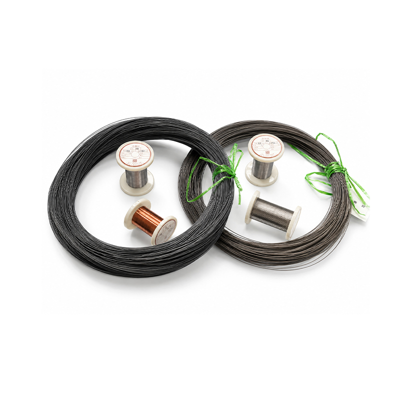 Thermocouple compensating wire alloy wireProduct Introduction Alloy wire for thermocouple compensating cables is a core conductive material for industrial temperature measurement systems, used as the alloy co...View Product →
Xinguo Group's stated background is relevant to these questions. The group reports operations covering alloy materials, cable, precious metals and instrument manufacturing, with around 300 employees and more than 50 technical staff, and it states that it operates ISO9001:2008, ISO14001:2004 and GB/T28001:2001 systems. Its product range includes eight alloy wire families, eight resistance thermometer variants covering abrasion-resistant, anti-corrosion, explosion-proof, multipoint explosion-proof, power station, sheathed, display and assembly designs, plus pressure gauge, flow meter, level instrument and instrument material categories. For a project that needs an infrared sensor verified with contact references, that breadth reduces the number of suppliers involved.
A practical approach for a first purchase is to order a modest quantity of thermocouple alloy wire or compensating wire alongside the instrument hardware, build two or three reference sensors in house, and compare them against an existing calibrated standard. This costs little and answers the questions that matter: how does the wire weld, how stable is the reading after thermal cycling, and how closely do two assemblies made from the same spool agree with each other.
For larger projects, confirm lead times and packaging before committing to a schedule. Wire that arrives on the wrong spool, with the wrong colour code, or with joints in the middle of a run creates rework that erases any saving on unit price. Clarify whether the supplier can deliver matched pairs, whether continuous lengths are guaranteed, and how the shipment is protected during transport.
Buy the reference chain and the measurement hardware from one manufacturer where possible, because the interface between instrument and alloy is where most unexplained offsets originate.
Industrial infrared sensors are used wherever the target cannot be touched: rotary kiln shells, moving webs and strip, molten metal and glass, high-voltage joints, sealed or sterile enclosures, and fast thermal cycles. In many of those applications the alternative is not a different sensor but no measurement at all.
A resistance thermometer with a calibrated Class A or Class AA element typically delivers a fraction of a degree of uncertainty in a stable process. An infrared sensor usually delivers a few degrees, with emissivity setting and spot fill contributing most of the difference. The gap narrows when the emissivity is verified and the target fills the spot.
It can, but not with a general-purpose long-wavelength instrument and an assumed emissivity. Bright metal reflects its surroundings into the sensor, which distorts the reading. Short-wavelength sensors, a modified sight path, or a surface treatment with known emissivity are the practical routes.
The ratio defines the spot size at a given distance. A 20:1 sensor at 2 metres measures roughly a 100 mm circle, and everything inside that circle is averaged into the result. For a small target, choose a higher ratio or reduce the working distance, and aim for the target to fill at least 1.5 times the nominal spot.
The 8 to 14 µm band handles general surfaces at moderate temperature. The 1.0 and 1.6 µm bands suit high-temperature metals. A 5.0 µm band is used for glass surfaces. A 3.9 µm band helps when the sight path crosses flame or combustion gases. The material and the environment decide the band, not the temperature alone.
Every six to twelve months is a reasonable baseline for stable processes, tightened to quarterly where the product mix, surface condition or quality limit demands it. Each check should be recorded with ambient temperature and lens cleaning status so the trend is comparable.
The usual cause is an emissivity setting that is too low, a spot that includes cooler background, or a dirty window and obstructed sight path. A comparison measurement on the same surface with a contact reference separates these causes quickly.
Yes, in most plants. Contact sensors provide the reference for verifying infrared readings, they cover stationary measurement points where accuracy matters, and they serve as backups when an optical path is temporarily obstructed by steam or dust.
Common base-metal thermocouple pairs include Type K, Type N, Type E, Type J and Type T, each with its own alloy chemistry and electromotive force curve. Compensating wire extends the same curve from the junction to the transmitter terminals, and resistance thermometers rely on stable element materials with matched lead wire to keep lead resistance from distorting the reading.
Manufacturers with in-house drawing capability typically supply thermocouple alloy wire, compensating wire, manganin, constantan, pure nickel, Monel and nichrome wire on spools or coils, with the minimum order quantity, tolerance band and insulation class agreed during specification. Confirming batch traceability and continuous length before ordering avoids most rework.
An infrared sensor solves the access problem, a contact sensor solves the accuracy problem, and a plant that owns both solves the verification problem.
Explore the product range and talk to the engineering team
Whether the next project is a single infrared sensor on a kiln shell or a full reference chain for a new production line, the same three decisions return: confirm the surface emissivity, confirm the spot size, and confirm how the reading will be verified. Everything else follows from those.

A kiln shell glowing at 950 °C, a plastic film running at 200 metres per minute, a molten aluminium stream behind a heat shield, a roller bearing buried inside a sealed gearbox. None of these targets will accept a probe, and none of them care whether your instrument has a nice c...

A heat-treatment line that replaced its protection tubes every six weeks did not have a thermocouple problem. It had a ceramic problem. The elements came out of service clean and unbroken, yet the tubes had cracked, spalled or bowed, and the drift that followed belonged to the t...
The first sign that something is wrong with a thin film RTD is rarely a dramatic failure. It is a slow disagreement with a neighbouring sensor, a reading that creeps during a heat-up cycle, or a batch trend that no longer matches the recipe. In one case, a food processor replace...
A dairy processor in eastern China spent three weeks chasing a pasteurizer fault that turned out to be one crossed thermocouple extension wire inside a junction box. The recorder kept writing believable numbers the whole time, which is precisely why the investigation took so lon...



 INQUIRY
 English
 عربى
 русский
 中文简体