A threaded RTD probe almost never fails at the point where it measures temperature. It fails where it touches the plant. A maintenance crew pulls one out of a glycol header on a Tuesday afternoon, finds the threads galled and the sheath slightly bent, and reorders from the same part number, only to discover that the replacement will not seat in the welded boss. The old unit was 1/2 in NPT; the new one is G1/2. They look the same on a bench, they start in the same way, and they leak at different pressures.
Here is the short version before the detail: on a threaded RTD probe, the thread decides whether the unit fits and seals, the sheath decides how fast it responds and how long it survives, and the element decides what accuracy you can honestly claim. Those three choices are not independent. A 3 mm sheath gives you a fast response and a fragile probe. A 12 mm sheath gives you a robust probe that reads slowly enough to miss a control loop's dynamics. Choose the thread first, because it is the one item you cannot adjust in the field.
Xinguo Group has manufactured temperature instruments and the alloy wire that goes inside them since 1997, and the questions that reach our engineering desk are rarely about platinum curves. They are about thread callouts, immersion depth, and whether a probe can come out of a line without a shutdown. This article works through those questions in the order a specification actually gets written, from the boss on the pipe to the terminals in the connection head.
The thread on a threaded RTD probe is a pressure-retaining mechanical joint, not a mounting convenience. That single fact explains most field problems. A sensor element that drifts by 0.3 °C is an annoyance; a thread that weeps solvent onto a hot line is an incident report.
Three unknowns have to be closed before anything else is specified. First, what is already on the vessel or pipe: a welded half-coupling, a threaded boss, a flanged nozzle, or nothing at all? Second, which thread standard governs that connection? Third, how does that thread form seal: on tapered thread flanks, on a parallel thread plus gasket, or on an O-ring face?
Most industrial threaded RTD probes use one of four interfaces: tapered pipe threads that seal on the threads themselves, parallel pipe threads that need a sealing washer, metric parallel threads with an O-ring or bonded seal, or a compression fitting that grips the sheath. Each behaves differently under thermal cycling. A tapered thread that has been tightened once tends to reseat in the same position, which is helpful. A parallel thread relies entirely on the gasket, so a missing or hardened washer becomes a leak rather than a nuisance.
Stainless steel threads gall. Two austenitic surfaces under load, with no lubricant and a little grit, can cold-weld in a way that turns a five-minute swap into a cutting job. A nickel-based anti-seize compound on the male thread, applied thinly and kept away from the process end, is ordinary practice on high-temperature installations. It is not a substitute for the correct thread, but it is the difference between a probe that comes out in three years and one that has to be drilled out.
Thread engagement matters as well. A probe with a long thread run into a shallow boss will bottom out on the sheath shoulder before the threads seal. A probe with a short thread in a deep boss leaves exposed threads that collect product and corrode. Ask for the thread length on the drawing, not just the thread callout, and measure the boss depth with a depth gauge rather than estimating it.
The confusion between 1/2 in NPT and G1/2 is the single most common ordering error we see. Both are nominally half-inch, both measure close to 21 mm across the thread crest, and both happen to run at 14 threads per inch. The similarity ends there. NPT has a 60 degree thread angle and a 1:16 taper; BSPP has a 55 degree thread angle and is parallel. A BSPP probe will start in an NPT boss for two or three turns, then bind. If someone forces it, either the boss or the probe is ruined.
| Thread callout | Standard | Approximate major diameter | Pitch | How it seals | Where it is typically found |
|---|---|---|---|---|---|
| 1/2 in NPT | ASME B1.20.1 | 21.3 mm | 14 TPI | Tapered, seals on thread flanks | North American process lines, general industry |
| 1/4 in NPT | ASME B1.20.1 | 13.7 mm | 18 TPI | Tapered | Compact housings and small manifolds |
| 3/4 in NPT | ASME B1.20.1 | 26.7 mm | 14 TPI | Tapered | Heavier wells and larger sheath diameters |
| G1/2 (BSPP) | ISO 228 | 20.955 mm | 14 TPI, 55 degree | Parallel, seals on a washer or gasket | European pipework and gland entries |
| R1/2 (BSPT) | ISO 7 | Approx. 20.9 mm at gauge plane | 14 TPI, 55 degree | Tapered | Legacy European and Asian plant |
| M20 x 1.5 | ISO 261 | 20 mm | 1.5 mm | Parallel, seals on O-ring or bonded washer | Instrument housings and DIN-style fittings |
| M27 x 2 | ISO 261 | 27 mm | 2 mm | Parallel | Larger European thermowells |
Two practical rules follow from the table. First, never assume a half-inch callout means a specific standard; ask for the standard number and check it with a ring gauge. Second, treat adapter bushings as a separate design decision. A bushing solves a mismatch in an emergency, but it adds a second sealing interface, moves the probe tip further out of the pipe, and introduces a dissimilar-metal joint that can loosen under vibration. If the plant has a mixed thread legacy, standardise on adapters at the boss rather than at the probe.
Metric threads deserve a note of their own. M20 x 1.5 is common on instrument housings and cable entries rather than on process connections, so a probe ordered with M20 x 1.5 is often designed to screw into a head or a protection tube rather than directly into a pipe. Confirm which interface the thread belongs to. A probe that threads into a housing and a probe that threads into a pressurised line may share a callout but not a pressure rating.
Response time is a thermal problem, not an electronic one. Heat has to travel from the process through the sheath wall, across the internal insulation, and into the element. The sheath diameter sets the distance, and the sheath material sets the conductivity. Nobody can change that with a faster transmitter.
The chart below shows representative 63 percent response times in stirred water for stainless steel sheathed probes of different diameters. Treat the numbers as a comparison tool rather than a guarantee; response time in air is far slower, and response time in a viscous product or through a thermowell wall is slower still.
The pattern is not linear. Going from 6 mm to 12 mm roughly triples the response time, while going from 6 mm to 3 mm only halves it. That asymmetry is why the 6 mm sheath is the default in most plants: it sits in the useful part of the curve, survives normal handling, and accepts a standard spring-loaded fitting.
Below 4.5 mm, the sheath becomes a handling item. A 3 mm mineral-insulated probe bends easily, which is an advantage in a cramped skid and a liability when someone uses the head as a lever. Minimum bend radius is roughly five times the diameter, and repeated bending work-hardens the stainless until it cracks. If the installation needs tight routing, specify the bend in the factory rather than in the field.
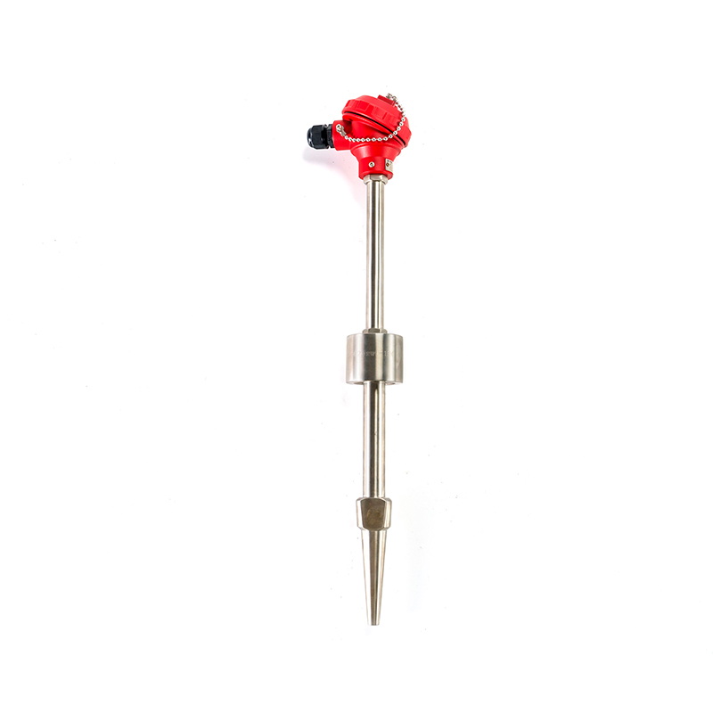
Xinguo's 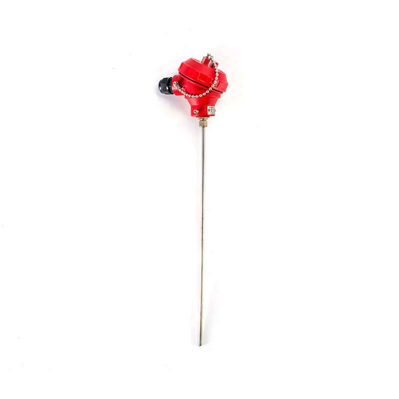 Mineral-Insulated Sheathed RTD for Fast, Durable Temperature SensingView this sheathed RTD when fast response and pressure resistance matter, and compare sheath wall thickness as well as diameter for durability.View Product →sheathed RTD range covers the diameters discussed here with mineral insulation and stainless or alloy sheaths, which is the usual starting point when a threaded connection has to be combined with a fast response. The trade-off to discuss with the supplier is not whether a thin sheath is faster, because it always is, but whether the process velocity and the maintenance habits will let it survive.
Wall thickness belongs in the same conversation. Two probes can both be called 6 mm and have different wall thicknesses, which changes both the pressure capability and the thermal path. A thin-wall sheath responds faster and dents more easily. Ask for the wall thickness rather than assuming the outside diameter tells the whole story.
A probe measures the temperature of its own tip. If the tip sits in a boundary layer, a wake, or a pocket of stagnant product, the reading describes that pocket rather than the process. Immersion depth is therefore a process decision dressed up as a mechanical dimension.
In a small pipe, the usual target is for the tip to pass the centreline, which puts it in the fastest-moving part of the flow and away from the wall. Going deeper than the far wall is pointless and adds vibration load. In large ducts and vessels, a common approach is to insert one third to one half of the way across, or to use a thermowell whose length is chosen from the same rule. Where the pipe is too small to allow that, a narrower sheath or an angled installation is a better answer than a shallow probe.
Stem conduction is the failure mode that makes shallow probes read low on hot lines and high on cold lines. Heat travels along the sheath from the process to the cooler connection head, and the element sits at the cold end of that gradient. A rough working rule is that immersion should be at least ten sheath diameters to keep the conduction error small in a well-insulated installation. A 6 mm probe therefore wants around 60 mm of immersed length, and a 12 mm probe wants around 120 mm. Shorten that and the error grows, sometimes by several degrees.
Insulation around the exposed head and the first part of the sheath is often more effective than adding length. A probe that is correctly immersed but has 100 mm of bare sheath and a head exposed to moving air will still lose heat along the stem. Lagging the connection head is not cosmetic.
Inside the sheath, the element choice is narrower than the marketing suggests. Pt100 is the default in industrial plants because 100 ohms at 0 °C is a well-known reference, the wiring is tolerant of reasonable lead lengths, and the standardisation behind IEC 60751 is deep. Pt1000 offers ten times the resistance, which reduces lead error in two-wire circuits and allows thinner films, but it also increases self-heating at a given excitation current.
Wire-wound ceramic elements handle higher temperatures and tend to be more stable over years. Thin-film elements are smaller and faster and now dominate below about 500 °C. Neither is universally better; the useful question is what the loop actually needs.
Accuracy class is where buyers most often overpay or under-specify. IEC 60751 defines tolerance bands by formula rather than by a single number, so the same class looks impressive near ambient and less impressive at 400 °C.
| Class | Tolerance formula | At 0 °C | At 100 °C | At 400 °C |
|---|---|---|---|---|
| AA | plus or minus (0.1 + 0.0017 x |t|) °C | 0.10 °C | 0.27 °C | 0.78 °C |
| A | plus or minus (0.15 + 0.002 x |t|) °C | 0.15 °C | 0.35 °C | 0.95 °C |
| B | plus or minus (0.30 + 0.0048 x |t|) °C | 0.30 °C | 0.78 °C | 2.22 °C |
Two clarifications save money. A tolerance class is a manufacturing limit, not a calibration certificate; if the loop needs traceability, ask for a calibration report at the working points rather than assuming class AA covers it. And buying class AA for a process that swings by five degrees is usually waste, while buying class B for a loop with a two-degree control band is a design fault.
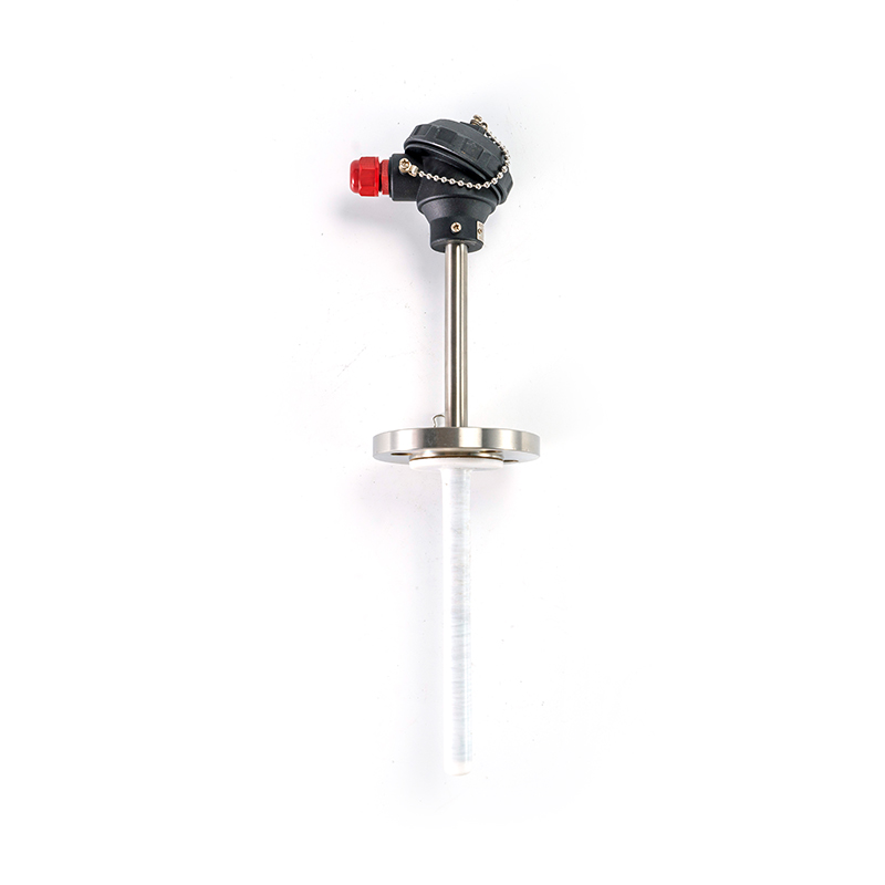
For assemblies where the element, the protection tube and the head are supplied together, Xinguo's 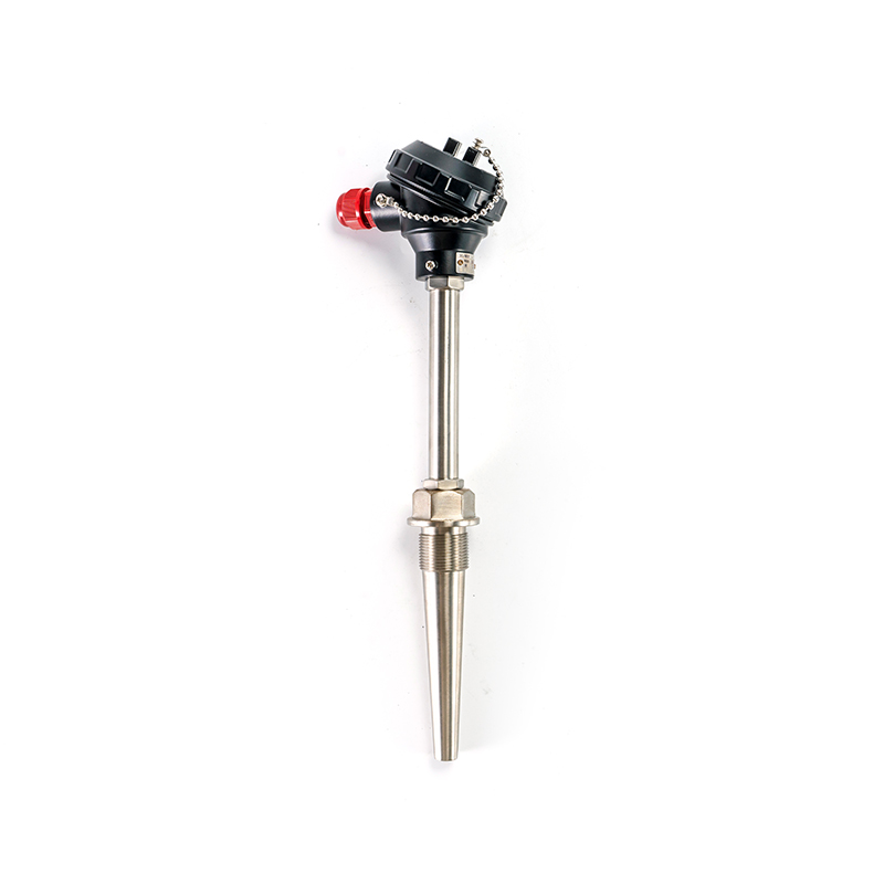 Factory-Matched Assembly RTD for Industrial and Laboratory Temperature MeasurementChoose this assembly RTD when element, protection tube and head are matched at the factory; check wiring and lead resistance before installation.View Product →assembly RTD range is the natural fit, since the element, the thread and the immersion length are matched at the factory instead of being combined on site. Where the process involves abrasive slurries or aggressive media, the same element can be supplied in a wear-resistant or corrosion-resistant sheath construction.
Lead resistance is invisible on a datasheet and obvious in a trend. A Pt100 element changes resistance by about 0.385 ohms per degree Celsius, so every ohm of loop resistance is worth roughly 2.6 °C. A two-wire connection adds both lead lengths to the measurement, and a 20 metre run of ordinary copper cable can easily contribute enough resistance to shift the reading by a degree or more.
Three-wire connection assumes the two leads are identical and subtracts one from the total, which works well when the cable is the same type and length. Four-wire connection measures the element voltage directly with a high-impedance input and is effectively immune to lead resistance, which is why laboratories and wide-range plant loops prefer it.
Practical guidance is straightforward. Short runs into a local transmitter can live with three wires. Long runs to a remote rack, or any loop with a narrow control band, deserve four. Two-wire belongs in indicator-duty applications where a degree of error does not change a decision.
The transmitter location matters as much as the wire count. Fitting a head-mounted transmitter moves the analogue signal problem to a short, controlled distance and sends a robust 4 to 20 mA signal down the long cable. That single change often improves a reading more than upgrading the element class. Where a head transmitter is used, check that the housing depth and the thread on the head are compatible with the probe body before ordering, because the head thread and the process thread are separate specifications.
Shielding deserves a mention because it is routinely mishandled. The cable shield should be grounded at one end, normally the panel end, to avoid circulating currents. Grounding both ends creates a loop that picks up exactly the noise the shield was meant to reject. On installations near variable-frequency drives, route the RTD cable away from motor cables rather than relying on the shield alone.
A threaded joint is convenient, not unlimited. Its pressure capability falls as the thread size grows, as temperature rises, and as the number of thermal cycles increases. A 1/2 in NPT joint on a small sheath may be perfectly adequate at 25 bar and 200 °C; the same style at 60 bar with frequent cycling is a leak waiting for a shutdown.
Temperature derates the joint in two ways. The thread compound or sealant loses elasticity, and the differential expansion between a stainless probe and a carbon steel boss opens clearance. Both effects are gradual, which is why leaks often appear after a plant has been running hot for months rather than on the first day.
Above roughly 40 to 50 bar, the conversation should move to a flanged connection or a welded thermowell with a separate probe. It is not that a threaded joint cannot hold; it is that the margin becomes thin enough that installation quality dominates the outcome, and installation quality varies by shift.
Flow velocity sets a second limit. A bare probe in a fast liquid stream behaves like a cantilever, and vortex shedding can excite vibration at the sheath's natural frequency. Short, thick sheaths resist this. Long, thin sheaths do not, and a thermowell designed for the flow is the correct answer rather than a stiffer probe.
Every threaded installation should be leak-checked at operating pressure and temperature, not only at ambient. A joint that passes a cold hydro test can still weep once the line reaches 180 °C.
In a classified area, the probe is part of the protection concept, not just a sensor. Two approaches dominate. Intrinsic safety limits the energy entering the circuit so that a fault cannot ignite the atmosphere, which allows ordinary probes with suitable approvals and a certified barrier or isolator. Explosion-proof enclosure protection contains an internal ignition inside a housing strong enough to withstand it and cool enough at the flame path that the surrounding gas does not ignite.
For a threaded probe, the practical consequences are specific. The connection head grows and becomes a sealing item in its own right, with a defined thread for the cover and a defined cable entry. The temperature class limits the maximum surface temperature at the sheath, which can rule out a high-wattage self-heating element. The installation instructions for the flame path become mandatory reading instead of paperwork.
Where multiple measurement points exist in one vessel, a multipoint explosion-proof assembly reduces the number of penetrations and the number of cable glands, which is often the deciding factor in a reactor or a large tank. The trade-off is that each point must still meet its own immersion requirement, and the assembly has to be oriented correctly on installation.
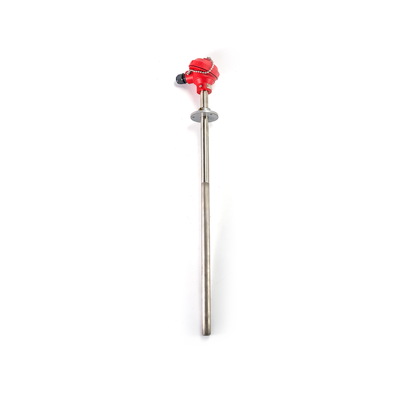
Xinguo's 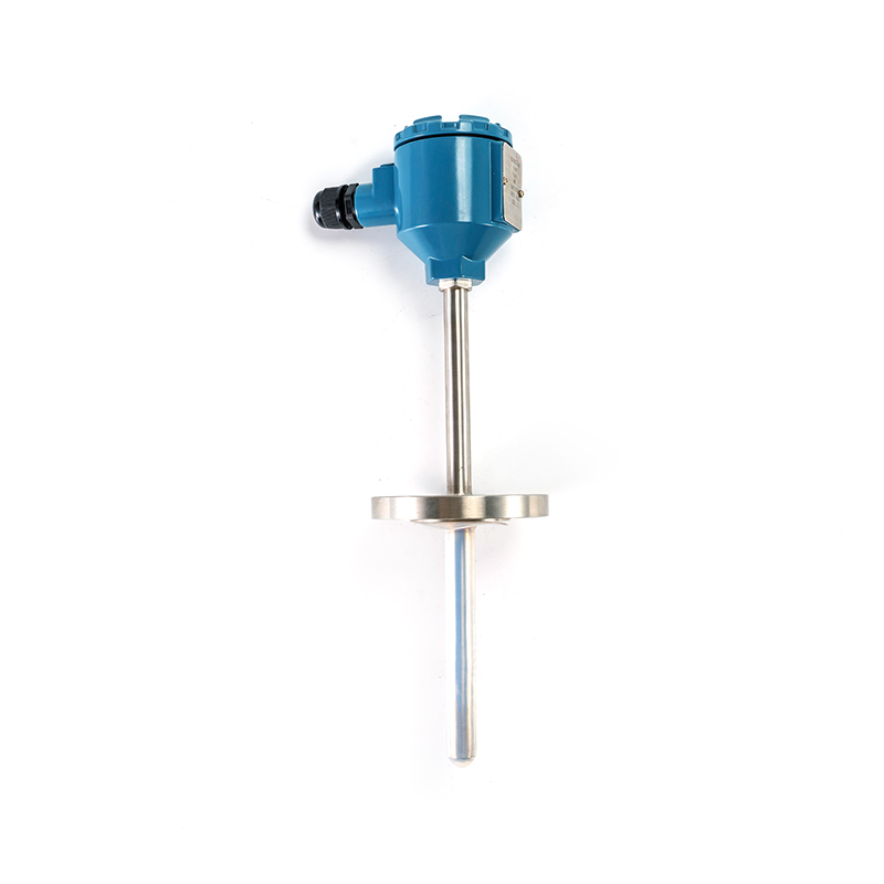 Explosion-Proof RTD for Hazardous Process Temperature MeasurementReview this explosion-proof RTD for hazardous areas; confirm area classification, gas group, temperature class and head ambient conditions, and check sheath material against the process.View Product →explosion-proof RTD range is built for these applications, with the housing, the thread and the certification treated as one assembly. The specification conversation should include the area classification, the gas group, the temperature class, and the ambient range around the head, because a probe that is certified but mounted where the head reaches 90 °C may still fall outside its own rating.
316 and 316L stainless steel cover most water, steam, solvent and food-grade duties and are the default for a reason. They are not universal. Chlorides above roughly 200 ppm at elevated temperature invite pitting, and a pitted sheath eventually becomes a path for moisture into the insulation.
For aggressive media, the options widen quickly: Inconel for high temperature and oxidation, Hastelloy for chlorides and mixed acids, PTFE coating for strong acids at moderate temperature, and ceramic protection tubes where the sheath must survive both heat and chemical attack. Each choice changes the thermal path, so a coating that solves corrosion may slow the response enough to matter in a control loop.
Abrasion is a separate problem from corrosion and needs a different answer. A slurry at speed removes stainless in months. A wear-resistant sheath with a hardened surface or a thicker wall buys time, and a removable well that can be replaced without draining the line buys more. Xinguo supplies abrasion-resistant RTD constructions alongside the standard sheathed range for exactly this reason.
Surface finish matters more than most specifications admit. In hygienic service, a rough sheath creates a cleaning shadow, and the thread itself is a difficult area to clean. Where cleanability is the driver, a flush-diaphragm or sanitary connection usually beats a threaded probe, even though the threaded version is cheaper to buy.
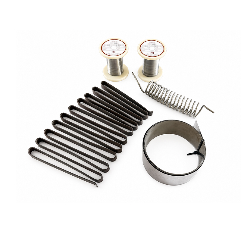
The alloy side of the supply chain deserves a mention because it affects stability. Element and lead wire drawn from controlled alloys, such as constantan, manganin, pure nickel and thermocouple alloy wire, behaves predictably over time. Xinguo's own alloy materials operation supplies these wires, which is why a probe and its internal wiring can be specified together rather than sourced from separate suppliers that never speak to each other.
Most of the accuracy bought at the specification stage is spent during installation. The pattern repeats across plants: the correct probe, the correct thread, and a reading that drifts because the head is full of condensation or the sheath is touching a pipe wall.
Torque values should come from the supplier rather than from feel. A stainless thread in a stainless boss will accept more torque than it should, and the damage appears later as a stretched thread or a cracked weld at the boss. Where a torque figure is not published, ask for one; a manufacturer that builds these assemblies daily usually has a table ready.
Commissioning deserves a baseline record: ambient reading before installation, reading at a known process condition, and insulation resistance of the element circuit. That baseline turns a future drift into a measurement rather than an argument.
A quotation is only as good as the information behind it. Sending a part number from an old drawing works until the drawing is wrong, which is common after a plant modification. The list below is the minimum set that lets a manufacturer quote without guessing, and it is the same list a wholesaler or distributor will ask for when they pass the enquiry upstream.
Two items on that list are routinely omitted and routinely cause rework: boss depth and flow velocity. A probe that is 20 mm too long will not fit, and a probe in a fast stream needs a different mechanical design even if every other parameter matches.
When comparing quotes from more than one supplier, compare the drawings rather than the prices. Two probes quoted as 6 mm by 150 mm with 1/2 in NPT can differ in wall thickness, thread length, element construction and head sealing, and those differences are where the cost sits. A supplier that will send a drawing with dimensions and tolerances before production is worth more than a small price advantage.
There is no single standard, but 1/2 in NPT dominates in North America and G1/2 appears widely in European pipework. M20 x 1.5 is more often a housing or cable entry thread than a process connection. Always specify the standard number along with the size, because the nominal size alone is ambiguous.
Not directly. The two threads share a nominal size and a 14 TPI pitch but differ in thread angle and taper. A G1/2 probe may start in an NPT boss and then bind, damaging both parts. Use a proper adapter at the boss if the plant has a mixed legacy, and remember that an adapter adds a second sealing interface.
A tapered thread such as NPT or BSPT can seal on its own flanks. A parallel thread such as G1/2 or M20 x 1.5 needs a washer, gasket or O-ring. If the probe must be removed while the line is live, a welded thermowell with a separate spring-loaded probe is the practical solution regardless of thread form.
For liquids in small pipes, aim for the tip to pass the centreline. As a general rule, immersion of at least ten sheath diameters keeps stem conduction error small, so a 6 mm probe wants around 60 mm of immersed length. Lagging the connection head reduces the error further and is often cheaper than a longer probe.
Four-wire removes lead resistance from the measurement and is the safest choice for long runs or narrow control bands. Three-wire is adequate for shorter runs and matched cables. Two-wire is acceptable only where a degree or two of error does not change a decision, since one ohm of lead resistance is worth about 2.6 °C on a Pt100.
Yes, but the protection concept covers the whole assembly. Intrinsic safety keeps energy low and allows a certified probe with a suitable barrier; explosion-proof protection contains an internal ignition inside a rated housing with a defined flame path. The head, the cable entry and the temperature class all become part of the specification.
Send the thread callout with its standard, immersion length from the sealing face, sheath diameter and material, element type and tolerance class, wiring configuration, process medium, maximum temperature and pressure, area classification and flow velocity. Add the boss depth if it is not a standard coupling, and ask for a dimensional drawing before production.
A threaded RTD probe is a small assembly with an unusually large number of interfaces: the thread to the boss, the sheath to the process, the element to the wire, and the head to the environment. Getting one of them wrong produces a symptom somewhere else, which is why thread and immersion details are worth settling before price.
The most useful habit in this work is to measure the boss before ordering anything. A thread gauge, a depth gauge and a note of the process temperature take ten minutes and prevent the most expensive kind of reorder, which is the one that arrives after the shutdown has started.

A threaded RTD probe almost never fails at the point where it measures temperature. It fails where it touches the plant. A maintenance crew pulls one out of a glycol header on a Tuesday afternoon, finds the threads galled and the sheath slightly bent, and reorders from the same ...

A kiln shell glowing at 950 °C, a plastic film running at 200 metres per minute, a molten aluminium stream behind a heat shield, a roller bearing buried inside a sealed gearbox. None of these targets will accept a probe, and none of them care whether your instrument has a nice c...
A heat-treatment line that replaced its protection tubes every six weeks did not have a thermocouple problem. It had a ceramic problem. The elements came out of service clean and unbroken, yet the tubes had cracked, spalled or bowed, and the drift that followed belonged to the t...
The first sign that something is wrong with a thin film RTD is rarely a dramatic failure. It is a slow disagreement with a neighbouring sensor, a reading that creeps during a heat-up cycle, or a batch trend that no longer matches the recipe. In one case, a food processor replace...



 INQUIRY
 English
 عربى
 русский
 中文简体