A maintenance team replaces a two wire sensor on a 60 m line with a three wire RTD, expecting the reading to land closer to the laboratory value. Instead it settles about 2.9 °C high. The element is inside tolerance, the transmitter has a fresh calibration sticker, and the wiring matches the drawing. Nothing is broken. What failed is the assumption behind the third lead: that the two current-carrying conductors have the same resistance.
Here is the conclusion up front. A three wire RTD removes lead resistance error only when the two measurement leads match closely in resistance. When they match, most of the copper error cancels and you get close to four wire performance at a lower conductor count. When they do not match, through different lengths, a splice, a corroded terminal or a mixed cable reel, the compensation is incomplete and you may end up with the accuracy you already had, plus one more conductor to maintain.
The rest of this article works through what the third lead does electrically, how much error it removes on a real installation, where a three wire RTD is the sensible engineering choice, and what to check before approving a purchase order. It is written for people who specify, install and maintain these sensors, not for a physics exam.
Strip away the terminology and an RTD is a resistor whose value changes predictably with temperature. A Pt100 sits at 100 Ω at 0 °C and rises roughly 0.385 Ω for every additional degree. The instrument's only job is to measure that resistance precisely. Almost all the difficulty in RTD wiring comes from one fact: measuring resistance means pushing a current through the element, and the wires carrying that current have resistance of their own.
In the common three wire layout, two leads land on one terminal of the element and a single lead lands on the other. One of the paired leads carries the excitation current. The other paired lead acts as a potential or sense lead: the input circuit reads the voltage at that terminal while drawing almost no current, so that conductor contributes almost no voltage drop. The third conductor carries the current back to the instrument.
What the instrument effectively sees is the element voltage plus the drop in the current lead plus the drop in the return lead, minus whatever the sense lead lets it subtract. The three wire arrangement subtracts one lead drop and assumes the other is identical. That is the whole trick. It is an arithmetic correction built on a physical assumption about your installation, not a second measurement of the error.
Take a Pt100 with 0.5 mm² copper leads, roughly 0.034 Ω per metre per conductor at room temperature. On a 50 m run each conductor contributes about 1.7 Ω. With two wires both conductors sit in the measurement path, adding 3.4 Ω. Divide by the 0.385 Ω/°C sensitivity and the reading is high by about 8.8 °C, which is far larger than the element's tolerance class. With three wires, the input circuit removes one 1.7 Ω lead on the assumption that the return lead matches it. If the two current leads are matched within 0.02 Ω, the residual error is around 0.05 °C. If they sit 0.10 Ω apart, the residual is roughly 0.26 °C.
Not every input circuit handles this identically. Some transmitters use two matched current sources and measure both lead drops separately; others subtract a single assumed lead resistance; PLC input cards vary as well. What they share is a dependence on the equality of your two current-carrying conductors. A sensor can be perfect and the compensation still poor, because the compensation lives in the electronics and the assumption lives in your cable.
Lead equality fails in unremarkable, everyday ways. A technician shortens one leg during a retrofit. Someone adds a junction box and a terminal strip on one side only. A fuse or surge arrestor goes into a single conductor. A terminal corrodes after three years in a humid cabinet. An extension cable turns out to be two core, so the third conductor is borrowed from a shared common. None of these show up on a loop drawing, and all of them reintroduce the error the third wire was bought to remove.
Lead resistance error hides well on paper, because copper looks like a perfect conductor until you multiply by a real distance. The figures below approximate a Pt100 with 0.5 mm² copper leads, element at 0 °C, and no compensation applied for the two wire rows.
Approximate added error from lead resistance, Pt100 with 0.5 mm² copper leads at 0 °C
Indicative values only; the actual result depends on conductor gauge, loop current and the input circuit design.
The shape of the chart is the argument for three wire RTDs. Two wire error scales with distance, while three wire error scales with mismatch, and mismatch on a well-built installation is a few hundredths of an ohm rather than a couple of ohms. The chart also shows why the configuration alone does not guarantee a result: a three wire sensor landed with a 10 m conductor on one leg and a 55 m conductor on the other behaves like neither row.
For buyers, this is the practical reason to pair the sensor and the lead set at the point of order, with the lead resistance stated on the documentation. Xinguo Group builds temperature instruments around that pairing, so the element, sheath and terminal arrangement are agreed together rather than assembled from three purchase orders and a hope. The four wire row at the bottom shows what remains when both lead drops are measured instead of assumed, and it is why laboratories keep paying for the extra conductor.
Putting the three configurations side by side makes the trade-off visible. The question is rarely which is most accurate in theory, but which one you can keep accurate for the next ten years with the maintenance team you actually have.
| Configuration | Conductors | How lead error is handled | Indicative error, 50 m | Typical fit |
|---|---|---|---|---|
| Two wire | 2 | Not handled; both lead resistances add directly to the measurement | About 8.8 °C | Short runs, indication only, embedded or disposable sensors |
| Three wire | 3 | One lead drop is subtracted on the assumption that the return lead matches it | About 0.05 to 0.3 °C when leads match | Most industrial process loops, general control, plant utilities |
| Four wire | 4 | Both lead drops are measured with separate sense conductors | Under 0.02 °C | Laboratory reference, custody transfer, high accuracy at long distance |
Read the accuracy column for what it says and what it does not. It describes lead error only. Element tolerance sits on top of that, along with self-heating, immersion depth, response time and the thermal path between the process and the element. A three wire RTD with a matched lead set and a Class A element is a genuinely accurate instrument. A three wire RTD on a long, unmatched lead set is a Class A element with a large unknown bolted to it, and no amount of calibration paperwork changes that.
Cost also deserves a plain answer. The third conductor is cheap compared with the engineering time spent chasing a two degree offset, but it is not free: three core shielded cable costs more than two core, the transmitter must support three wire input, and terminal blocks need a third position. Four wire doubles the cable requirement and narrows the transmitter choice again, which is why it tends to appear only where the accuracy case is strong and the run is long.
Most temperature loops in a plant are not chasing hundredths of a degree. They are chasing repeatability, a stable reading and a sensor that survives the environment. That is exactly the territory the three wire RTD was designed for.
Four wire wins wherever the measurement is the point rather than a supporting signal. Reference thermometry, calibration baths, custody transfer and laboratory work all justify measuring both lead drops instead of assuming one. Long runs above roughly 100 m with tight accuracy targets also push toward four wire, because the assumption of exact lead equality becomes harder to hold across that distance and across seasonal temperature swings in the cable tray.
Short runs of a few metres, embedded sensors inside compact equipment, indication-only panel meters and high-volume products where the transmitter has no three wire input are all cases where two wire is correct. The error on a 3 m run with 0.5 mm² cable is roughly 0.5 °C, and if the process tolerance is ±5 °C, spending on a third conductor buys nothing. The mistake is not choosing two wire; it is choosing it on a 40 m run and then wondering why the trend sits two degrees above the handheld reading.
Copper resistance also drifts with ambient temperature, about 0.4 percent per °C. On a two wire run the resistance of both leads moves with the cable tray temperature, so a warm afternoon produces a slow offset that looks like a process change. On a matched three wire run that drift largely cancels, because both current leads move together. This is one of the quieter benefits of the configuration and one that rarely appears in a specification sheet.
If the third lead works by assumption, then everything that protects the assumption is part of the instrument's accuracy. Lead matching is not an installation nicety; it is the measurement.
Three core shielded cable with copper conductors in the 0.5 mm² to 1.5 mm² range covers most plant work. Twisted conductors help against induced noise, and a foil or braid shield helps in cabinets with drives and contactors. Insulation choice follows the environment: PVC for a dry cabinet, PTFE or fibreglass where radiant heat or chemical exposure is present. One rule that catches people out is the use of thermocouple extension wire on an RTD circuit. Those alloys are selected for thermoelectric behaviour, not for low, stable resistance, so keep RTD leads copper throughout.
Before the sensor is dressed into the tray, measure lead-to-lead resistance with a milliohm meter and write it on the loop sheet. A reading taken at commissioning becomes a baseline; two years later, if the trend drifts, the same measurement tells you whether the cable or the element moved. Without a baseline, a drifting three wire RTD usually ends in a replacement, which may not address the cause.
The excitation current on a Pt100 is usually between 0.1 mA and 1 mA, so the signal voltage is small and the input is sensitive. Keep RTD cables out of the same tray as motor feeders and variable frequency drive output cables, cross power cables at right angles where crossing is unavoidable, and bond the shield at one end to avoid a ground loop. These are standard practice, but they are also the first thing skipped when a shutdown window closes early.
A correctly specified three wire RTD can still deliver two wire results if the work around it undoes the assumption. These are the failures that show up most often during troubleshooting.
Bench calibrators commonly simulate a two wire RTD, which forces the loop current through a jumper or a single test lead. If the resistance of that test path does not match the transmitter's internal compensation assumption, the simulated temperature is not the temperature being applied, and the calibration bakes in an offset. Use a three wire simulation with matched test leads, or verify with a resistance decade box and separate sense connections. It is a small procedural detail with a large effect on the loop's credibility.
Compensation happens where the wiring meets the electronics. A head-mounted transmitter compensates for the short leads inside the connection head, which means the long run to the control room is a current loop and immune to lead resistance. Move the same transmitter to a DIN rail in the cabinet and the three wire compensation now stretches over the full cable run, which is a different problem with a different tolerance. Neither arrangement is wrong, but the drawing must match the one you built.
Excitation current heats the element slightly, and in still air inside a dry thermowell the effect can reach a few tenths of a degree. In a flowing liquid it is negligible. Immersion depth matters just as much: a sheath that is too short conducts heat down the stem from the process connection and reads low. A common working rule is an immersion length of at least ten sheath diameters, or 50 mm to 75 mm minimum in liquid service.
It happens more than anyone admits. A transmitter configured for three wire input with only two conductors landed will either read a fixed offset or fail its lead-break diagnostic, depending on the design. When a reading looks plausible but wrong, check that all three conductors arrived, are in the correct terminals, and are tight.
Wiring gets the signal home; the sheath keeps the element alive long enough to be useful. The same three wire connection can sit inside very different mechanical packages, and the choice between them is usually dictated by what the process does to metal.
A sheathed RTD packs the element into a compact stainless tube, often 3 mm to 8 mm in diameter, which bends around obstructions and responds quickly because the thermal mass is small. An assembly style RTD uses a replaceable insert inside a protective thermowell, so the element can be swapped without breaking into the process. For lines that are cleaned, sterilised or simply too important to open on a whim, the assembly approach usually wins on maintenance cost alone.
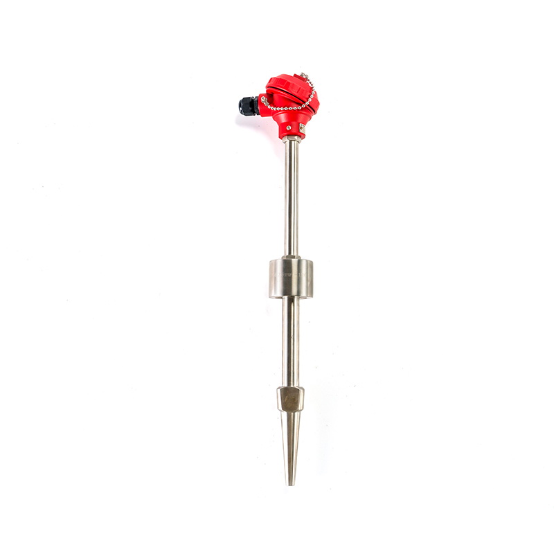
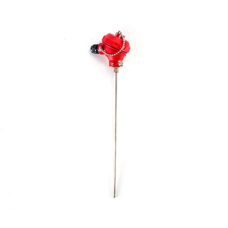 Compact Sheathed RTD for Industrial Temperature MeasurementCompact stainless-sheathed RTD offers fast thermal response and flexible installation for industrial temperature measurement where quick response and durability matter.View Product →
Where flammable gas or dust may be present, the connection head and housing become part of the safety case rather than an accessory. Explosion proof designs contain an internal fault within an enclosure rated to do so, and the certification markings on the label must match the area classification on the drawing. Multipoint versions pack several elements at different depths in one sheath, which suits tall vessels and reactors where a single point tells only part of the story.
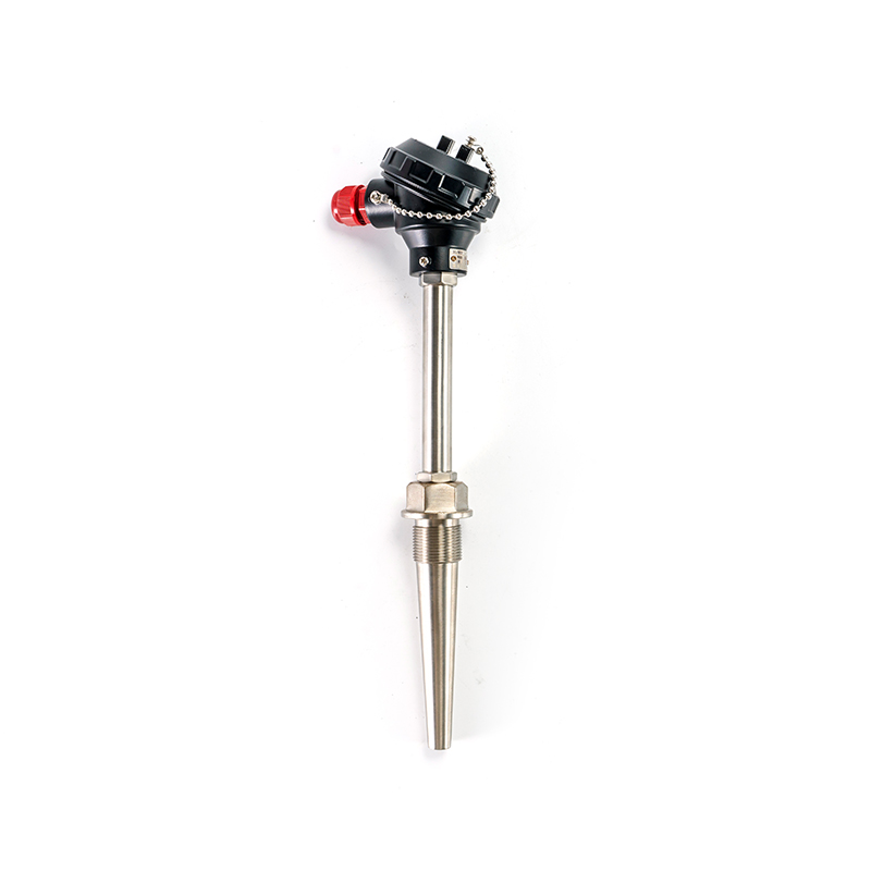
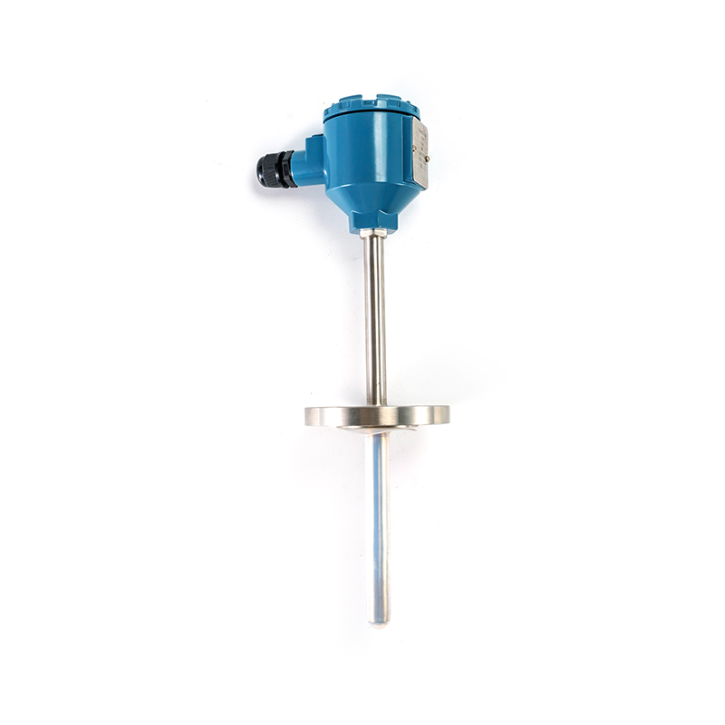 Explosion-Proof RTD for Hazardous Process Temperature MeasurementExplosion-proof RTD is designed for hazardous areas and direct temperature measurement in liquids, steam, gases and solid surfaces across process industries.View Product →
Slurries, fly ash and catalyst fines erode a standard stainless sheath in months. Abrasion resistant constructions add a hardened outer layer or a heavier wall, and the payoff is measured in replacement intervals rather than datasheet numbers. In chemically aggressive service the answer is usually a different sheath alloy or a non-metallic protection layer, chosen against the actual concentration and temperature rather than a generic corrosion chart.
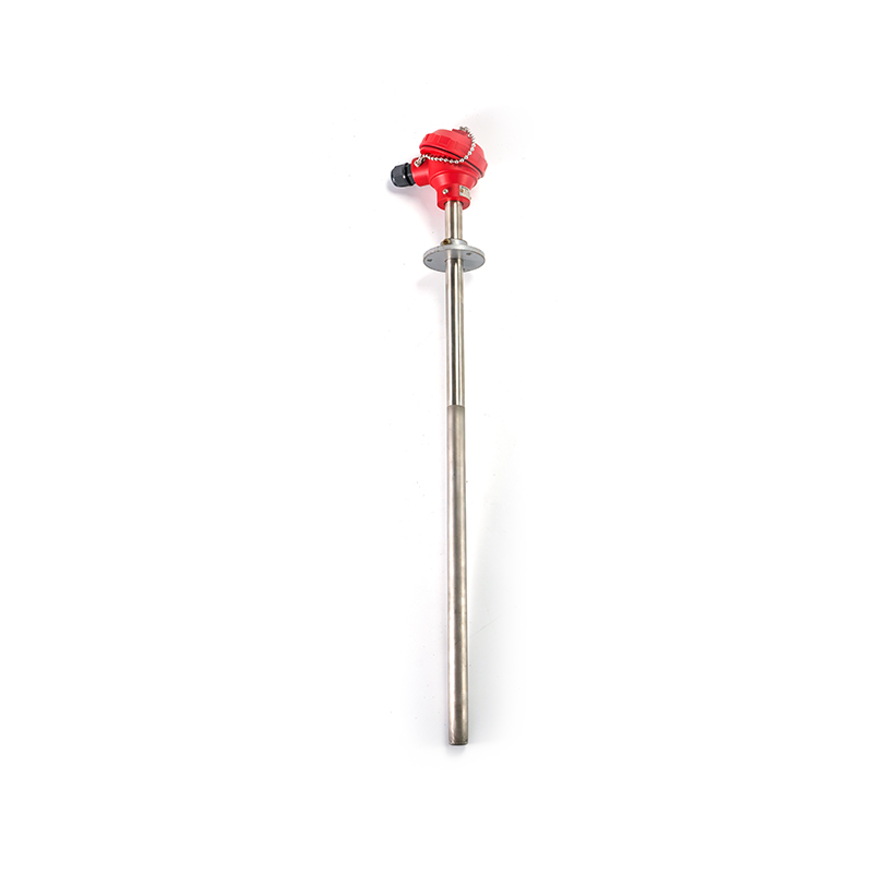 Abrasion-Resistant RTD for Wear-Prone Industrial Temperature MeasurementAbrasion-resistant RTD uses wear-protection materials and robust construction for temperature measurement in erosive, high-temperature environments such as kilns and fluidized beds.View Product →
One practical point ties the mechanical and electrical choices together. Whatever the sheath, the three leads still need to be matched and documented, and the terminal head is where that either happens cleanly or turns into a nest of spliced wire. For abrasive, corrosive or hazardous duty, Xinguo Group supplies the temperature instrument and the connecting arrangement together, so the lead treatment is defined before the sensor reaches the site rather than improvised at the flange.
Most sourcing problems come from a specification that named the element but left the wiring, the sheath and the documentation to chance. The list below covers what is worth writing down before a request for quotation goes out.
For OEMs and project buyers the questions then shift from principle to supply. Can the manufacturer hold a tolerance band across a five hundred piece order, not just across a sample? Can the supplier state lead resistance per unit rather than per catalogue page? Can the wholesaler or distributor deliver the same three wire configuration in six months, when the spare parts budget finally releases? These are commercial questions, but they decide whether the accuracy you specified survives the first year of operation.
temperature instrumentsIt also helps to buy the element and the lead set from one source. When the sensor and its connection arrangement come from different suppliers, a lead mismatch becomes a conversation between two warranty departments instead of a measurement on a bench. Xinguo Group manufactures both the alloy materials and the finished temperature instruments, which shortens that path considerably when a project needs a non-standard length or a specific terminal arrangement.
It is the standard choice for industrial temperature loops where the sensor sits some distance from the transmitter or input card. By subtracting one lead drop and assuming the other matches, it removes most of the cable resistance error that would otherwise make a two wire reading useless beyond a few metres.
Count the conductors that terminate at the element or the connection head, not the ones at the cabinet. Three wire designs show two leads on one element terminal and one on the other. A quick resistance check between leads also helps: two leads that read close to the element resistance with the others open indicate the paired side.
Yes, but you lose the compensation and inherit the full lead resistance error. The usual approach is to tie the sense lead to the current lead at the transmitter, which turns the sensor into a two wire device. It is acceptable on short runs and poor practice on long ones.
The compensation assumes equal resistance, so unequal lengths leave a residual error equal to the difference. Even a modest difference of 0.1 Ω translates to roughly 0.26 °C at 0 °C for a Pt100, which matters in tight control loops and matters less in a ±5 °C process.
Not strictly. It can run directly to a PLC input card that provides three wire measurement. A head-mounted transmitter is often better on long runs, because it converts the resistance to a current loop at the sensor and makes the cable length irrelevant to the temperature reading.
There is no fixed number, because length matters only through lead resistance and mismatch. Runs of 50 m to 100 m are routine with 0.5 mm² copper and a matched lead set. Beyond that, check the input circuit's allowable lead resistance and consider four wire if the accuracy target is tight.
It changes the lead resistance per metre and therefore the size of the error you are trying to cancel. A heavier gauge reduces total lead resistance, which helps, but the matching between the two current leads matters more than the absolute value.
Copper resistance rises about 0.4 percent per °C, so lead resistance moves with ambient temperature. On a properly matched three wire circuit both current leads move together and the effect largely cancels. A drift that tracks cabinet temperature usually points to a mismatch, a loose terminal or a shared common.
A three wire RTD is a good engineering compromise, and it stays good only while the two current leads stay equal. The configuration removes almost all lead resistance error on a matched installation, costs one extra conductor, and works with the input cards and transmitters already installed in most plants. What it cannot do is correct for a cable that was cut unevenly, a terminal that loosened, or a sensor chosen without regard to the environment around it.
Before the next order, three things are worth writing into the specification: the lead resistance you expect per conductor, the tolerance class and its test certificate, and the sheath construction that matches the process. That combination is what makes the difference between a temperature reading you trust and one you re-check every quarter. If you are working through a specific loop, a non-standard length or a hazardous area requirement, the team at Xinguo Group can align the element, the lead set and the mechanical package before anything ships.
contact
A maintenance team replaces a two wire sensor on a 60 m line with a three wire RTD, expecting the reading to land closer to the laboratory value. Instead it settles about 2.9 °C high. The element is inside tolerance, the transmitter has a fresh calibration sticker, and the wirin...

A threaded RTD probe almost never fails at the point where it measures temperature. It fails where it touches the plant. A maintenance crew pulls one out of a glycol header on a Tuesday afternoon, finds the threads galled and the sheath slightly bent, and reorders from the same ...
A kiln shell glowing at 950 °C, a plastic film running at 200 metres per minute, a molten aluminium stream behind a heat shield, a roller bearing buried inside a sealed gearbox. None of these targets will accept a probe, and none of them care whether your instrument has a nice c...
A heat-treatment line that replaced its protection tubes every six weeks did not have a thermocouple problem. It had a ceramic problem. The elements came out of service clean and unbroken, yet the tubes had cracked, spalled or bowed, and the drift that followed belonged to the t...



 INQUIRY
 English
 عربى
 русский
 中文简体