Thermocouple Types, Structure, and Selection Guide for Industry
Thermocouple Basics: Direct Answer and Practical Overview
The direct answer is that a thermocoupleis a temperature sensor made from two dissimilar metal wires joined at one end, generating a small voltage that changes predictably with temperature through the Seebeck effect. This voltage signal is then read by an instrument or transmitter and converted into a temperature reading, which is why thermocouples remain one of the most widely used sensing technologies across industrial, laboratory, and process environments. Choosing the correct thermocouple type depends primarily on the expected temperature range, the surrounding atmosphere, and the required accuracy, since different wire alloy pairs respond differently under oxidizing, reducing, or inert conditions.
This article reviews common thermocouple types and their characteristics, explains the working principle and internal structure, outlines application scenarios and selection guidance, presents a detailed type comparison, and closes with maintenance guidance and frequently asked questions. A qualified China manufacturer or China supplier typically stocks multiple thermocouple types and compensation cable grades to match varied industrial requirements, and understanding these distinctions helps buyers specify the right sensor rather than defaulting to a single familiar type. Three data visualizations are included to illustrate type distribution, response behavior, and multi-factor performance comparison.
Key takeaway: Thermocouple selection should start from temperature range and atmosphere compatibility, not from wire availability or habit.
Common Thermocouple Types and Their Characteristics
Thermocouples are classified by letter designations that indicate the specific alloy pair used to form the junction, and each type carries a distinct temperature range, accuracy class, and environmental compatibility profile. Type K, made from nickel-chromium and nickel-alumel wires, is the most widely used general-purpose thermocouple due to its broad temperature range and good oxidation resistance. Type J, using iron and constantan wires, offers a narrower range but performs well in reducing atmospheres and vacuum conditions. Type N was developed to improve on Type K's stability at high temperatures, while Type T, using copper and constantan, is favored for low-temperature and cryogenic applications because of its stable behavior near and below freezing.
Type K (Chromel-Alumel): general-purpose, wide range, good oxidation resistance.
Type J (Iron-Constantan): suited to reducing atmospheres, narrower upper range.
Type N (Nicrosil-Nisil): improved high-temperature stability over Type K.
Type T (Copper-Constantan): stable at low and sub-zero temperatures.
Type E (Chromel-Constantan): high output signal, useful in cryogenic to moderate ranges.
Type S/R (Platinum-Rhodium): high-temperature precision applications, often used as reference standards.
A professionalChina producer supporting multiple industries usually maintains inventory across several of these types, since power generation, petrochemical, and metallurgical customers each favor different combinations based on their specific thermal and atmospheric conditions. Selecting the correct type from the outset avoids accuracy drift and premature junction degradation later in service.
Table 1: Common thermocouple types and general temperature range reference.
Type
Alloy Pair
Typical Range
Type K
Nickel-Chromium / Nickel-Alumel
-200 to 1260 degrees C
Type J
Iron / Constantan
-40 to 750 degrees C
Type T
Copper / Constantan
-200 to 350 degrees C
Type S/R
Platinum-Rhodium
0 to 1600 degrees C
Key takeaway: Each thermocouple type has a defined temperature envelope and atmosphere preference, so type selection must match the actual process condition.
Working Principle and Internal Structure
A thermocouple generates a small measurable voltage whenever there is a temperature difference between its measuring junction and its reference junction, a phenomenon known as the Seebeck effect. The two dissimilar metal wires are welded or fused together at the tip to form the hot junction, while the opposite ends connect to measuring instrumentation through compensation or extension cables that must match the same alloy pair to avoid introducing measurement error. The voltage produced is very small, typically in the millivolt range, so signal conditioning and cold-junction compensation inside the connected instrument are essential for accurate temperature conversion.
Structural Components
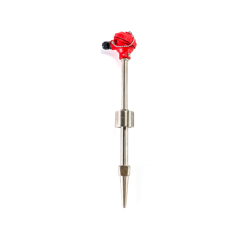
Beyond the sensing wires themselves, a complete industrial thermocouple assembly usually includes a protective sheath or thermowell, mineral insulation such as magnesium oxide packed around the wires, and a connection head housing the terminal block. The protective sheath, often made from stainless steel or a high-temperature alloy, shields the sensing wires from mechanical damage, corrosive atmospheres, and process fluid contact. Mineral insulated (MI) construction improves response time and durability compared with older ceramic-bead designs, since the compacted insulation conducts heat efficiently while maintaining electrical isolation between the wire pair.
Hot junction: the welded tip where the temperature-dependent voltage originates.
Protective sheath: shields wires from mechanical and chemical exposure.
Mineral insulation: improves thermal response while maintaining electrical isolation.
Connection head and terminal block: interfaces with compensation cable and instrumentation.
Key takeaway: Accurate temperature measurement depends on matched compensation cabling and proper cold-junction compensation, not just the sensing wires alone.
Data Visualization: Thermocouple Type Usage Distribution
Before examining the chart below, it helps to understand why certain thermocouple types dominate industrial usage more than others. Type K sees the widest adoption because it balances a broad temperature range with reasonable cost and good oxidation resistance across most general industrial settings. Type J remains common in older installations and reducing-atmosphere processes where its specific alloy behavior is preferred. Type S and Type R occupy a smaller share because platinum-rhodium construction is generally reserved for high-precision or high-temperature reference applications. Type T and Type N fill specialized niches related to low-temperature stability and improved high-temperature drift resistance respectively.
The column chart above reflects a general industrial usage pattern discussed across instrumentation industry references rather than one proprietary dataset. Type K's leading share is consistent with its status as the default general-purpose sensor across power, chemical, and manufacturing plants, where its wide range and moderate cost make it a practical first choice. Type J's continued relevance is tied to legacy installations and applications where reducing atmospheres favor its specific alloy chemistry over Type K. Type N's smaller but meaningful share reflects growing adoption in facilities upgrading from Type K to reduce long-term calibration drift at sustained high temperatures. Type T maintains a steady niche in refrigeration, cryogenic research, and food processing environments where sub-zero stability matters most. The combined share of Type S, Type R, and other precision types remains comparatively small because these sensors are reserved for calibration laboratories and specialized high-temperature processes such as glass or metal melting. This distribution also varies somewhat by region and industry sector, since aerospace and metallurgical customers tend to specify precision types more frequently than general manufacturing plants. A China wholesale buyer sourcing a mixed thermocouple order should expect Type K and Type J to make up the majority of typical industrial procurement volume. Recognizing this pattern helps buyers evaluate whether a supplier's stocked inventory aligns with common demand or leans toward more specialized, lower-volume types. Overall, the chart confirms that type selection in practice is driven by a combination of temperature range, atmosphere, and application legacy rather than any single dominant factor.
Application Scenarios and Selection Guide
Selecting the right thermocouple begins with defining the process temperature range, the surrounding atmosphere, and the required response speed and accuracy class. A furnace or kiln application operating at sustained high temperatures generally calls for Type K, Type N, or a platinum-rhodium type depending on the exact ceiling temperature and precision requirement. A refrigeration or cryogenic research application instead favors Type T for its documented stability at low and sub-zero temperatures. Fast-response measurements, such as monitoring rapid temperature changes in a reactor, benefit from thinner sheath diameters or exposed-junction designs, while robust industrial installations typically require a grounded or ungrounded junction inside a heavier protective sheath for mechanical durability.
High-Temperature Process Zones
Furnaces, kilns, and metallurgical processes typically require Type K, Type N, or platinum-rhodium types combined with a heavy-duty protective sheath rated for the expected ceiling temperature.
Low-Temperature and Research Zones
Cryogenic research, cold storage, and food processing applications commonly rely on Type T for its documented stability near and below freezing conditions.
Response time is another important selection factor, since a thicker sheath or mineral insulation layer slows the sensor's reaction to rapid temperature changes, while a thin, exposed-junction design responds faster but sacrifices mechanical protection. For applications with vibration or mechanical stress, a durable sheath material and properly supported lead wires reduce the risk of premature wire fatigue at the junction. A reliableOEM factory supporting multiple industries typically offers configurable sheath length, diameter, and connection head style so the sensor can be matched precisely to the installation point rather than forcing a standard design into an unsuitable location. Compensation cable selection matters equally, since using a cable with a mismatched alloy pair introduces a parasitic junction that distorts the temperature reading regardless of sensor quality.
Key takeaway: Matching thermocouple type, sheath design, and compensation cable to the specific process condition is more important than selecting based on familiarity alone.
Data Visualization: Response Time Behavior Across Sheath Configurations
Response time is one of the most practical performance factors engineers evaluate when specifying a thermocouple for a fast-changing process. The area chart below illustrates a general relationship between sheath diameter and the time required for a sensor to reach a stable reading after a step temperature change. This relationship follows well-documented heat transfer principles rather than a single proprietary test, since thicker metal masses inherently take longer to reach thermal equilibrium with their surroundings. Comparing exposed-junction, thin-sheath, and heavy-sheath configurations side by side clarifies the trade-off between speed and mechanical durability. Readers should treat the values as general engineering reference points rather than guaranteed figures for any specific product model.
The area chart shows response time increasing steadily as sheath mass and protective layering increase, moving from a fast-reacting exposed-junction tip toward a slower thermowell-fitted configuration. Exposed-junction designs respond quickest because the sensing wires have direct contact with the process medium, but this design sacrifices mechanical protection and is generally limited to controlled laboratory or short-term testing environments. Thin-sheath configurations offer a practical middle ground, providing reasonable protection while keeping thermal mass low enough for moderately fast response in many industrial control loops. Standard sheath designs, which represent the most common industrial installation, trade additional response time for significantly improved durability against mechanical stress and chemical exposure. Heavy sheath configurations extend service life further in harsh environments but introduce a more noticeable lag, which must be accounted for in fast process control algorithms. Thermowell-fitted installations show the slowest response because the sensor does not contact the process medium directly, relying instead on heat transfer through the thermowell wall, though this configuration allows sensor replacement without interrupting the process. Engineers working with high-speed control loops typically compensate for slower configurations by adjusting controller tuning parameters rather than always defaulting to the fastest possible sensor design. This trade-off between speed and durability is a recurring theme in Technology and process instrumentation, discussed broadly across industrial measurement literature. A China supplier offering configurable sheath diameters and thermowell options allows buyers to balance these factors according to their specific control requirements rather than accepting a fixed compromise. For most standard industrial monitoring points where response speed is not the primary constraint, a standard or heavy sheath configuration remains the practical default choice. Ultimately, the chart reinforces that response time should be evaluated alongside durability requirements rather than optimized in isolation.
Detailed Comparison of Thermocouple Types
Comparing thermocouple types side by side highlights why no single type serves every industrial application equally well. The table below summarizes temperature range, atmosphere suitability, and relative signal output across four commonly specified types, providing a practical reference for narrowing down a selection before consulting detailed manufacturer datasheets.
Table 2: Comparative reference across common thermocouple types.
Type
Atmosphere Suitability
Relative Signal Output
Type K
Oxidizing / Inert
Moderate
Type J
Reducing / Vacuum
Moderate
Type T
Oxidizing / Inert
Low
Type S/R
Oxidizing / Inert (High Temp)
Low
Key takeaway: Atmosphere compatibility often narrows the practical type choice as much as temperature range does, especially in reducing or vacuum conditions.
Data Visualization: Multi-Factor Performance Comparison
A radar-style comparison is useful when several performance factors need to be evaluated together for a single thermocouple type rather than read across separate table rows. The chart below focuses on Type K, since it is the most broadly specified general-purpose thermocouple across industrial applications. Temperature range, cost efficiency, response speed, and mechanical durability all factor into why Type K remains a common default choice. Viewing these factors together helps explain trade-offs rather than treating any single property as the deciding factor. This visualization complements the type comparison table above by examining one type in more depth.
The radar chart shows Type K scoring strongly on temperature range and cost efficiency, which explains why it remains the default choice across such a wide variety of industrial applications. Durability also scores relatively well, since the nickel-chromium and nickel-alumel alloy pair holds up reasonably well against oxidizing atmospheres common in many plant environments. Response speed sits at a moderate level, reflecting typical sheathed industrial construction rather than a fast-reacting exposed-junction configuration. Signal stability is generally solid but not the highest among all thermocouple types, since Type K is known to experience a phenomenon called short-range ordering that can cause minor calibration drift within a specific mid-range temperature band during extended high-temperature exposure. This is one reason Type N was developed, aiming to reduce that specific drift behavior while retaining a similar overall range and cost profile. Comparing this radar profile with a Type S or Type T profile would reveal a different shape entirely, with signal stability and precision peaking for Type S at the expense of cost efficiency. This balanced but imperfect profile is intentional rather than a shortcoming, since Type K was never designed to be the highest performer in every category, only a broadly practical compromise. For sourcing purposes, requesting a similar specification comparison from a China producer can help buyers weigh Type K against Type N or Type J for their specific application. This approach is particularly useful when a facility is evaluating whether to upgrade existing Type K installations to Type N for improved long-term stability. Overall, the radar chart reinforces that thermocouple type selection is a balancing exercise across range, cost, speed, and stability rather than a single optimization target.
Maintenance and Calibration Guidance
Routine inspection and periodic calibration are essential for maintaining thermocouple accuracy over time, since junction drift and insulation degradation can occur gradually without obvious external signs. Visual inspection should check the protective sheath for corrosion, pitting, or physical damage, particularly at installations exposed to corrosive process fluids or repeated thermal cycling. Insulation resistance testing between the sensing wires and the sheath can reveal moisture ingress or insulation breakdown before it causes erratic readings. Comparing readings against a reference standard at a known temperature point, such as an ice bath or calibration furnace, helps confirm the sensor remains within its expected accuracy class.
Sheath Inspection
Check for corrosion, pitting, or scaling on the protective sheath, especially after prolonged exposure to corrosive process media.
Insulation Resistance Test
Measure resistance between wires and sheath periodically to detect moisture ingress or insulation degradation early.
Reference Point Check
Verify readings against a known reference temperature point on a regular schedule to confirm calibration accuracy.
Compensation cable connections should also be checked regularly, since loose terminals or corroded contacts at the junction box can introduce measurement error that mimics sensor drift even when the thermocouple itself remains within specification. Replacement intervals vary depending on process severity, but sensors operating continuously near their upper temperature limit generally require more frequent calibration checks than those used in moderate, stable conditions. Working with a reliableODM supplier that documents alloy composition and manufacturing tolerances makes it easier for maintenance teams to set realistic calibration intervals based on actual material specifications rather than generic assumptions carried over from unrelated applications.
Key takeaway: Regular sheath inspection, insulation testing, and reference calibration together catch most thermocouple accuracy issues before they affect process control.
Manufacturing Background and Supporting Product Range
Consistent thermocouple performance depends heavily on alloy wire quality and precise junction fabrication at the manufacturing stage. Xinguo Group Co., Ltd., founded in 1997 and headquartered in Tianchang City, Anhui Province, operates as a high-tech enterprise whose subsidiaries include Anhui Xinguo Instrument Co., Ltd. and Anhui Xinguo Alloy Co., Ltd., among others, supporting an integrated approach to temperature instrument and precision alloy production. The Group engages in the research, development, production, and sales of temperature instruments alongside pressure, level, and flow instrumentation, and its product range extends to power cables, control cables, and compensation cables that are directly relevant to thermocouple installation and signal integrity.
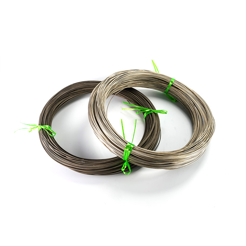
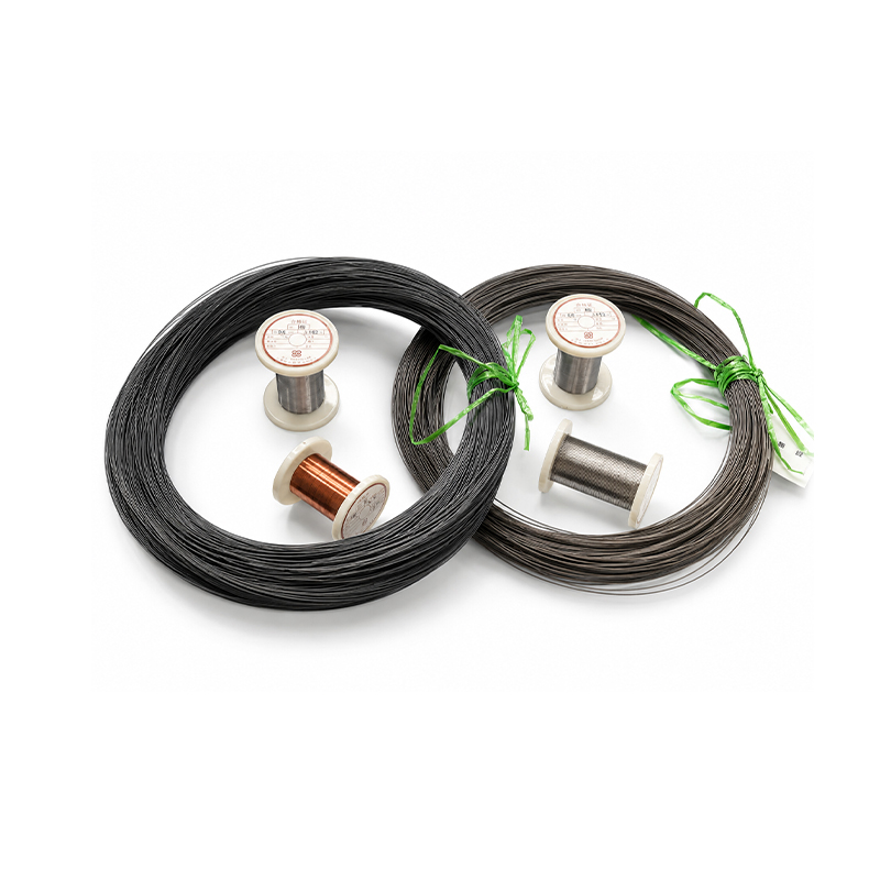
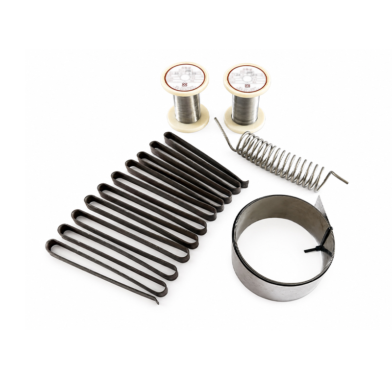
Anhui Xinguo Alloy Co., Ltd., a subsidiary dedicated to manufacturing precision alloy materials, produces thermocouple alloy wires across K, N, E, J, and T types along with corresponding compensation alloy wires such as KX, EX, NX, JX, and TX, in addition to pure nickel wires and other specialty alloys. This alloy-level manufacturing capability is significant for thermocouple performance, since wire composition consistency directly affects the accuracy and stability of the voltage signal generated at the hot junction. As a council member of the Instrument Materials Branch of China Instrument & Control Society, the subsidiary supports applications spanning aviation, petroleum, chemical engineering, and power industries. A China exporter or OEM/ODM factory with this level of vertical integration, from raw alloy wire through finished instrumentation, is generally better positioned to maintain tight tolerances across an entire thermocouple assembly rather than sourcing wire and sheath components separately from unrelated suppliers.
Key takeaway: Vertically integrated alloy and instrument manufacturing supports tighter consistency across a complete thermocouple assembly compared with sourcing components separately.
Frequently Asked Questions About Thermocouples
Q1: Which thermocouple type is suitable for general industrial use?
Type K is the most commonly specified general-purpose thermocouple due to its wide temperature range, reasonable cost, and good oxidation resistance across many industrial atmospheres.
Q2: Why does compensation cable matter for thermocouple accuracy?
Compensation cable must match the same alloy pair as the thermocouple type, since a mismatch introduces a parasitic junction that distorts the temperature signal before it reaches the instrument.
Q3: Can thermocouples be customized for specific installation requirements?
Yes, an OEM manufacturer or ODM manufacturer can typically configure sheath length, diameter, connection head style, and junction type based on drawings or installation specifications provided by the buyer.
Q4: How often should a thermocouple be recalibrated?
Calibration frequency depends on process severity, with sensors operating continuously near their upper temperature limit generally requiring more frequent checks than those used in stable, moderate conditions.
Q5: What causes inaccurate thermocouple readings over time?
Common causes include insulation degradation, loose or corroded terminal connections, mismatched compensation cable, and gradual alloy drift from prolonged exposure near the sensor's upper temperature limit.
Q6: How should buyers evaluate a new thermocouple supplier?
Buyers should review alloy wire specifications, request calibration and accuracy class documentation, and confirm the China factory maintains consistent process control across wire drawing, junction welding, and assembly stages.
A heat-treatment line that replaced its protection tubes every six weeks did not have a thermocouple problem. It had a ceramic problem. The elements came out of service clean and unbroken, yet the tubes had cracked, spalled or bowed, and the drift that followed belonged to the t...
The first sign that something is wrong with a thin film RTD is rarely a dramatic failure. It is a slow disagreement with a neighbouring sensor, a reading that creeps during a heat-up cycle, or a batch trend that no longer matches the recipe. In one case, a food processor replace...
A dairy processor in eastern China spent three weeks chasing a pasteurizer fault that turned out to be one crossed thermocouple extension wire inside a junction box. The recorder kept writing believable numbers the whole time, which is precisely why the investigation took so lon...
A heat-treat line running at 900 degrees Celsius will usually consume a Type K thermocouple in eight to fourteen months. The same probe sitting in a clean water loop at 90 degrees Celsius often survives eight years or more. Nothing about the two probes looks different on a datas...





 INQUIRY
 English
 عربى
عربى русский
 中文简体
中文简体