A stainless-steel probe on a pasteurizer reads 71.8 °C while a calibrated handheld reference shows 72.4 °C. Half a degree sounds harmless until that line has a 0.5 °C quality limit and the batch gets held for review. Nine times out of ten, the probe is not broken. The reading is being pushed off by a two-wire connection, a shallow immersion depth, or a tolerance class that nobody checked when the spare was ordered.
That is the practical side of the question what is an RTD. An RTD, or resistance temperature detector, is a temperature sensor built around a metal element whose electrical resistance rises in a predictable, repeatable way as it gets hotter. Feed a small, stable current through the element, measure the voltage across it, do a little maths, and you have a temperature reading that holds up over years of service.
The short version is this: RTDs are the sensor of choice when you need stability and accuracy in the −200 °C to 600 °C band, when you can tolerate a slightly slower response than a thermocouple, and when the reading has to stay trustworthy without constant re-calibration. Everything below explains how that works, where the accuracy actually comes from, and what to put on a purchase specification so the sensor you receive behaves like the one on the datasheet.
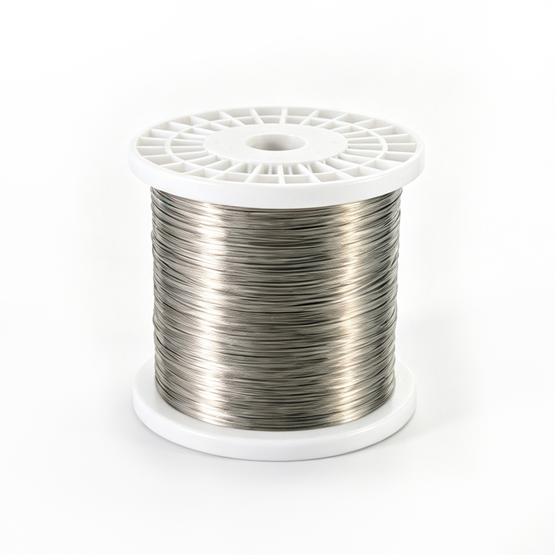
An RTD is a temperature sensor containing a sensing element made from a pure metal, most often platinum, whose resistance increases almost linearly with temperature. The most common version is the Pt100: 100 ohms at 0 °C, roughly 138.5 ohms at 100 °C, and about 0.385 ohms of change for every degree Celsius. The Pt1000 uses the same platinum but with 1000 ohms at 0 °C, which gives a larger signal and suits long cable runs or low-power transmitters.
Platinum dominates because it is chemically stable, can be drawn into very pure wire, and behaves consistently over a wide span. Nickel elements are cheaper and more sensitive per degree, but they drift more and top out around 300 °C. Nickel-iron elements appear in specialised low-temperature work. For general industrial measurement, when someone asks what an RTD is, they almost always mean a platinum resistance element in a protective sheath.
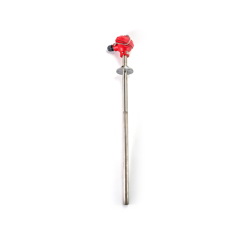
It helps to separate the parts, because buyers often confuse them:
An RTD is not a thermocouple. A thermocouple generates a tiny voltage from the junction of two dissimilar metals; an RTD changes resistance. They look similar from the outside, they both screw into a thermowell, and they are frequently mixed up on a bill of materials. The measurement physics, the accuracy profile and the required wiring are entirely different.
The physics is straightforward. Metals scatter electrons more energetically as temperature rises, so resistance climbs. For platinum the relationship is close enough to linear that engineers can use a simple slope for rough work: about 0.385 ohms per degree for a Pt100. For anything requiring real accuracy, the curve is described by the Callendar–Van Dusen equation, which corrects for the slight non-linearity above 0 °C and the more pronounced curve below it. Every commercial transmitter and every credible calibration certificate is built on that equation, standardised in IEC 60751.
Two practical details decide whether the reading is good:
You cannot measure resistance without pushing current through the element, and that current warms the element slightly. Typical excitation is 0.1 to 1 mA. In still air a 1 mA current through a small thin-film element can raise it by a fraction of a degree; in a fast-flowing liquid the error disappears almost entirely. Good transmitters use pulsed or low-current excitation, and good specifications state the self-heating coefficient so you can calculate the worst case for your process.
This is where most field errors come from. Copper lead wire has its own resistance, and in a two-wire connection it adds directly to the measurement. With a Pt100, one extra ohm of loop resistance looks like roughly 2.6 °C of error, and that error moves with ambient temperature as the cable warms and cools. A three-wire circuit compensates for equal lead resistances; a four-wire circuit eliminates lead resistance entirely and is the right choice for long runs, low spans or high-accuracy work.
Response speed matters too. A sheathed 6 mm probe in a thermowell typically reaches 90 percent of a step change in 10 to 30 seconds, depending on diameter, wall thickness and how well it contacts the well. Thinner sheaths and spring-loaded inserts respond faster; heavy protection is a trade-off against speed, not a free upgrade.
Wire-wound elements wrap a fine platinum coil around a ceramic former. They are stable, handle higher temperatures well, and are less prone to long-term drift, but they are more sensitive to vibration and generally larger. Thin-film elements deposit a platinum layer onto a ceramic substrate and laser-trim it to value. They are smaller, faster, cheaper in volume and much more resistant to shock — which is why the vast majority of industrial probes sold today use thin-film technology. For a vibration-heavy skid or a cement kiln, thin-film is usually the sensible choice; for a reference-grade calibration bath, wire-wound still has a place.
The tube protects the element, so it has to match the process. Type 304 stainless covers clean water and air. Type 316 stainless handles most mild chemicals and food-contact duties. Inconel 600 and similar alloys are used for high-temperature or aggressive service. PTFE-sheathed probes suit strongly acidic media at moderate temperatures. Diameter drives both response time and mechanical strength: 3 mm probes are fast but fragile, 6 mm is the industrial workhorse, and 8 mm or larger is used where flow-induced vibration or heavy handling is expected.
In a plant, the head is where reliability is won or lost. A cast aluminium or stainless head with a proper gasket keeps moisture out; a cheap plastic cover with a tired seal lets it in, and a wet terminal block produces exactly the kind of slow, drifting error that gets blamed on the element. Where a head-mounted transmitter is fitted, the resistance signal travels only a few centimetres before becoming a robust 4–20 mA loop — a real advantage on long cable runs or in electrically noisy areas.
All three devices measure temperature, but they win in different parts of the plant. The table below summarises the practical differences that matter when you are writing a specification or replacing an existing sensor.
| Property | RTD (Pt100) | Thermocouple (Type K) | Thermistor |
|---|---|---|---|
| Typical range | −200 to 600 °C | −200 to 1260 °C | −50 to 150 °C |
| Accuracy at 100 °C | ±0.1 to ±0.3 °C | ±1.5 to ±2.5 °C | ±0.1 to ±0.2 °C |
| Output signal | Resistance change | Microvolts | Large resistance change |
| Long-term stability | Excellent | Moderate, drifts with age | Good within range |
| Response speed | Moderate | Fast | Fast |
| Typical wiring | 2, 3 or 4 wire | 2 wire, special cable | 2 wire |
Reading a chart of accuracy side by side makes the gap clearer than a paragraph of description. The figures below use typical industrial values at 100 °C, where most process control loops actually sit.
Typical accuracy at 100 °C — shorter bar means tighter accuracy
The comparison is not an argument that thermocouples are bad sensors. A Type K junction will survive 1100 °C in a cement kiln where no platinum element would last a week, and it responds faster to a step change. What the chart shows is that in the moderate band, a standard Class A Pt100 delivers roughly an order of magnitude better accuracy than a standard thermocouple, and it holds that accuracy for years without a reference junction or cold-junction compensation to worry about. Thermistors are accurate but confined to a narrow range, which rules them out of steam service. For anything above roughly 600 °C, the practical answer shifts to thermocouples; our guide to choosing a sheathed thermocouple covers sheath, junction and grounding details for those cases.
The tolerance class is the single most overlooked line on an RTD datasheet, and it usually explains why two probes that look identical behave differently. IEC 60751 defines the classes by a tolerance value at 0 °C plus a slope that widens the band as temperature moves away from zero.
| Class | Tolerance at 0 °C | Practical note |
|---|---|---|
| AA | ±0.10 °C | Laboratory and custody-transfer work; fragile and costly |
| A | ±0.15 °C | The usual choice for critical process loops |
| B | ±0.30 °C | General industrial service; most common stock item |
| C | ±0.60 °C | Rough indication, alarm points, non-critical monitoring |
Three further specification items decide whether the installed sensor performs like the one on the test bench:
The pattern across industries is consistent: RTDs appear wherever temperature is a quality variable, a safety limit or an efficiency lever, and where the range stays below the point where platinum stops being practical.
In power generation, feedwater, condensate, bearing and stator winding temperatures are monitored continuously. These measurements feed control loops and protection logic, so drift is not just an inconvenience — it can trip a unit. A purpose-built element with a robust sheath and a stable class rating is the norm here.
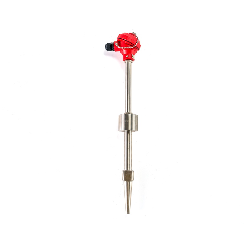 RTD for Power Station Temperature MonitoringA separation-type RTD with elastic pressing for boilers, turbines, heat exchangers and other critical power-plant measurements requiring stable, reliable temperature sensing.View Product →
In chemical and petrochemical plants, the sensor often meets acids, caustics or chlorine-bearing atmospheres. A standard 316 sheath may last months. Barrier coatings, PTFE sheaths or alloy tubes extend service life and reduce the maintenance loop where a probe is replaced every shutdown.
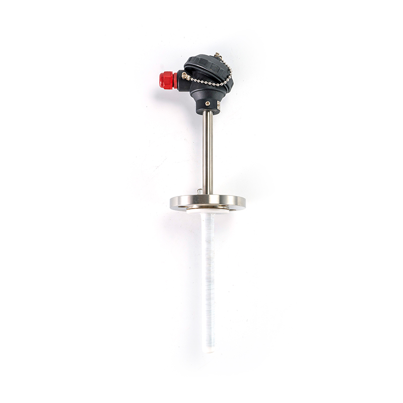 Anti-Corrosive RTD for Harsh Chemical EnvironmentsCorrosion-resistant RTD offered in aluminum, zinc and suitable alloys for acidic or alkaline water, chemical processing and water treatment temperature measurement.View Product →
Where flammable gas or dust is present, the enclosure and circuit design become the deciding factor. An explosion-proof assembly keeps the arc inside the housing and prevents a flammable atmosphere from being ignited, which is a certification question rather than a sensing question — but it must be settled before the purchase order, not after.
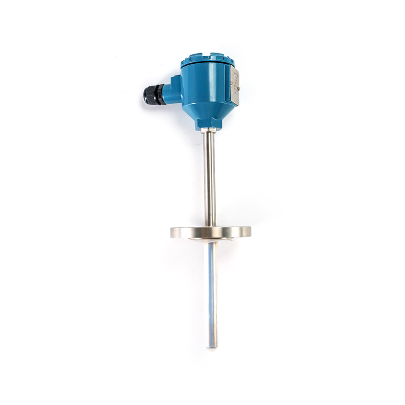 Explosion-Proof RTD for Hazardous Process EnvironmentsA temperature sensor for flammable gas, vapor or dust areas, measuring liquids, steam, gases and surfaces from 0°C to 1300°C in refineries and chemical plants.View Product →
Other places RTDs quietly do the work: motor and generator windings, bearing housings, HVAC supply and return lines, food and beverage pasteurizers and CIP circuits, pharmaceutical clean utilities, and semiconductor cooling loops. In each case the reason is the same — a stable resistance signal that a standard transmitter or PLC card can read without special compensation.
In practice, the failures that reach the maintenance backlog follow a short and repetitive list:
None of these require a better sensor. They require a specification and an installation check that take the wiring, the immersion and the environment into account at the design stage, which is far cheaper than discovering them during a shutdown.
Whether you are sourcing a single spare or negotiating a frame agreement with a manufacturer or supplier, the same ten lines on a specification prevent most disputes:
Buyers who work through these points once usually find that a single detailed specification serves several production lines, and that spares standardisation cuts both inventory and the risk of fitting the wrong probe during a night shift.
It is a temperature sensor built from a metal element whose electrical resistance increases as it gets warmer. Measure the resistance accurately, convert it using a standard curve, and you have a temperature reading. The most familiar version is the Pt100, which reads 100 ohms at 0 °C.
Resistance Temperature Detector. The name matters because it tells you what signal to expect: resistance, not voltage. That determines the transmitter type, the wiring configuration and the kind of input card the control system needs.
An RTD changes resistance with temperature and is more accurate and more stable in the moderate range. A thermocouple generates a small voltage at the junction of two dissimilar metals and works to much higher temperatures, at lower accuracy and with more drift over time.
A Class B element is within ±0.30 °C at 0 °C, Class A within ±0.15 °C, and Class AA within ±0.10 °C. The permitted error widens as temperature moves away from 0 °C, so always evaluate the class at your actual operating temperature rather than at the calibration point.
Two-wire connections add the lead resistance to the measurement. Three-wire circuits compensate for equal lead resistances and are the industrial default. Four-wire circuits eliminate lead resistance completely and are used for long runs, low spans and high-accuracy work.
An explosion-proof or intrinsically safe assembly with the appropriate certification for the gas group and temperature class. The sensing element itself is the same; the enclosure, circuit energy limits and certification are what make the assembly suitable for the area.
It depends on criticality and service conditions. Clean, stable duties can run several years between verifications, while corrosive or high-vibration service may justify an annual check. Many plants set the interval from the first two calibration results rather than from a generic schedule.
The question of what an RTD is has a one-sentence answer, but the answer that saves money is longer. An RTD is a platinum resistance element inside a protective sheath, and its real-world accuracy comes from four decisions made before it is installed: which tolerance class you specified, how many wires you ran, how deep the probe sits in the process, and whether the sheath material suits the medium.
Get those four right and the sensor becomes the least interesting item on the line, which is exactly what a temperature sensor should be. Get them wrong and the same sensor becomes a recurring maintenance ticket, replaced repeatedly while the real fault sits in a terminal block or a shallow thermowell. For buyers working across multiple lines, standardising on a small number of element classes and sheath materials usually delivers more reliability than chasing the tightest tolerance available.

A stainless-steel probe on a pasteurizer reads 71.8 °C while a calibrated handheld reference shows 72.4 °C. Half a degree sounds harmless until that line has a 0.5 °C quality limit and the batch gets held for review. Nine times out of ten, the probe is not broken. The reading is...

A sterilizer chamber reads 121 °C on the panel while the independent chart recorder says 124 °C. The maintenance team spends a morning chasing steam valves and traps before someone finally checks the temperature sensor, which turns out to be the only thing on the skid that was q...
A maintenance team replaces a two wire sensor on a 60 m line with a three wire RTD, expecting the reading to land closer to the laboratory value. Instead it settles about 2.9 °C high. The element is inside tolerance, the transmitter has a fresh calibration sticker, and the wirin...
A threaded RTD probe almost never fails at the point where it measures temperature. It fails where it touches the plant. A maintenance crew pulls one out of a glycol header on a Tuesday afternoon, finds the threads galled and the sheath slightly bent, and reorders from the same ...



 INQUIRY
 English
 عربى
 русский
 中文简体