You open the junction head of an industrial temperature sensor and find two sets of lead wires instead of one. That is the first clue that you are looking at dual element RTD wiring. A dual element RTD contains two electrically independent resistive temperature detectors inside the same housing or thermowell, and the way those elements are connected determines whether you get redundancy, an averaged reading, or two separate signals for process control and protection.
The short answer to most dual element RTD wiring questions is simple: treat each element as a separate RTD. Each element has its own resistance versus temperature characteristic, and each element can be connected to its own transmitter, controller, or safety system. What makes dual element wiring more interesting is how you apply that independence in the field.
This guide covers dual element RTD wiring fundamentals, 2-wire, 3-wire, and 4-wire connections, common configurations, transmitter hookup, redundancy logic, installation practices, calibration, and troubleshooting. It also includes selection advice for armored, assemble, and explosion-protected designs so you can wire confidently without guessing.
A dual element RTD is a resistance temperature detector that contains two separate platinum sensing elements in the same protective tube, sheath, or assembly. Each element is typically a thin-film or wire-wound platinum resistor with a nominal resistance of 100 ohms at 0 °C, commonly called a Pt100. The two elements are electrically isolated from each other and from the metal sheath, so they can be used completely independently.
Each element has its own set of lead wires. A dual element RTD therefore has two, three, or four lead wires per element, depending on the internal connection style. The most common dual element Pt100 sensors have six wires: three wires for element one and three wires for element two. Eight-wire versions with four wires per element are available for instrumentation that demands true four-wire accuracy on both elements.
The mechanical construction may be an assembly type with a terminal head, a sheathed type with a flexible mineral-insulated cable, or an explosion-proof type with a flameproof enclosure. The sensing elements are usually positioned close together so both represent the same process temperature point. That physical proximity is what makes dual element RTDs attractive for safety-critical and redundant measurements in a single process penetration.
The dual element design does not change the fundamental physics of an RTD. Both elements still follow the same resistance-temperature curve, usually defined by the IEC 60751 standard for platinum. If one element drifts, fails, or needs calibration, the other element remains available for measurement, which is the central practical benefit.
The decision to install a dual element RTD is usually driven by redundancy, space constraints, or the need to connect the same temperature point to multiple control and monitoring systems. A single element RTD gives you one resistance signal and one point of failure. A dual element RTD gives you two independent signals from the same process location, which is a significant operational advantage.
| consideration | Single Element RTD | Dual Element RTD |
|---|---|---|
| Redundancy | None | Two independent elements |
| Process penetration | One thermowell needed | One thermowell needed for two signals |
| Space required | Compact | Similar footprint to single element |
| Wiring complexity | Lower | Higher, with separate lead sets |
| Maintenance impact | Sensor failure stops measurement | Second element can keep plant running |
| Typical cost | Lower | Moderately higher |
| Common use cases | Non-critical monitoring | SIS, turbine bearings, process safety |
There is a common misunderstanding that dual element RTDs are only for high-safety industries such as power generation or oil and gas. In practice, they are also used whenever a process engineer wants a local temperature indicator and a remote DCS signal from the same point, without adding a second thermowell. The small additional sensor price is often lower than the cost of drilling another nozzle into a vessel or pipeline.
You should also consider that a dual element RTD cannot fully replace two separately installed RTDs if those RTDs need to be located in different physical positions. If the goal is to measure the same point with two sensors, the dual element is a simpler choice. If the goal is to compare temperature at two different locations, use two separate single or dual element sensors.
Each element inside a dual element RTD can be wired in the same way as a single RTD. The wiring method determines how accurately the measuring circuit can compensate for lead wire resistance. For a dual element sensor, the number of lead wires doubles accordingly.
In a 2-wire connection, two wires connect to the element, and the measured resistance includes the resistance of the lead wires. This method is only acceptable for short cable runs and low accuracy requirements because lead resistance changes with ambient temperature and causes measurement error. A dual element RTD with two wires per element has four external wires total.
In a 3-wire connection, three wires are connected to one end of the element and one common wire. The measurement circuit measures the resistance of one lead and subtracts it from the total loop. This is the most common industrial compromise because it gives good lead compensation without requiring a dedicated current and voltage pair. A dual element Pt100 with three wires per element has six external wires.
In a 4-wire connection, two wires supply a constant current and two separate wires measure voltage across the element. This eliminates lead resistance error completely, making it the most accurate method. A dual element RTD with four wires per element has eight external wires, which is less common but necessary for high-precision metering and laboratory applications.
| Wiring per element | Total wires for dual element | Lead resistance error | Best used for |
|---|---|---|---|
| 2-wire | 4 wires | High | Short local connection, status indication |
| 3-wire | 6 wires | Low | Plant DCS, PLC analog input modules |
| 4-wire | 8 wires | None | High-accuracy calibration, critical measurement |
The physical colors of the leads vary by manufacturer, but a common convention is to use one color pair for element one and another color pair for element two. Before terminating, always confirm the lead assignment with the sensor data sheet. If you mix up the elements, you may still get valid readings but you lose the intended redundancy mapping.
From a wiring perspective, treat element one as RTD A and element two as RTD B. Keep the two sets of leads separated in the junction head and along the cable route to reduce the risk of accidental short circuits and to simplify future troubleshooting.
Once you understand that each element is an independent RTD, the wiring configurations are easy to organize. The most common industrial configurations are independent dual measurement, redundant measurement for safety, and separate process / display signals.
Element one connects to the main control system through a temperature transmitter. Element two connects to a local indicating transmitter or a vibration monitoring system. This is the typical choice for motor bearings, gearboxes, and compressors where the same bearing temperature needs to reach both the protection relay and the asset management system.
Both elements are connected to separate analog input cards or separate safety PLCs. If element one fails open, element two continues to provide the process temperature. Redundant wiring must include separate junction head terminals, separate cables, and ideally separate power supplies to achieve true diversity.
One element feeds the DCS for process control, while the second element feeds a panel meter or HMI display. This avoids loop isolation cards and allows maintenance staff to verify the process reading without touching the control loop.
Less common configurations include connecting two elements in series to get an approximate average resistance, or in a bridge to measure a temperature difference. These methods are rarely used in modern digital systems because a transmitter can calculate average or difference electronically with better precision.
When you plan the wiring diagram, label every terminal clearly. Use separate wire colors for each element and designate a common shield ground for the cable. A dual element RTD with six leads can look intimidating, but a clear wiring diagram removes most of the risk.
The most practical question in dual element RTD wiring is how to make the final connection to a transmitter. Many temperature transmitters have one RTD input; a dual element sensor then needs two transmitters. Other transmitters have dual RTD inputs and can accept both elements directly.
Before wiring, check the transmitter input configuration. A standard single-input RTD transmitter has terminals such as 1, 2, 3, and 4 for a three-wire RTD. If you connect a dual element sensor to two single-input transmitters, each element uses its own set of terminals. If you use a dual-input transmitter, you simply assign element one to input A and element two to input B.
The most common and economical field arrangement is two head-mounted transmitters installed inside the RTD connection head. This keeps the analog signal strong and local, and lets you run two separate 4–20 mA loops back to the control room. The dual element RTD's six wires are terminated at the transmitter terminals or a terminal block, and each transmitter produces an independent current loop.
When switching between two elements, make sure that the transmitter configuration matches the sensor’s resistance curve and wiring method. For example, if you select a three-wire Pt100 input, the transmitter must see three leads from one element only. Do not combine leads from both elements into one transmitter input.
A robust dual element sheathed RTD with mineral insulation is often preferred for transmitter mounting because the cable bends easily and the sensing tip keeps both elements at the same position. This style also reduces response time compared to a large-bore assembly type.
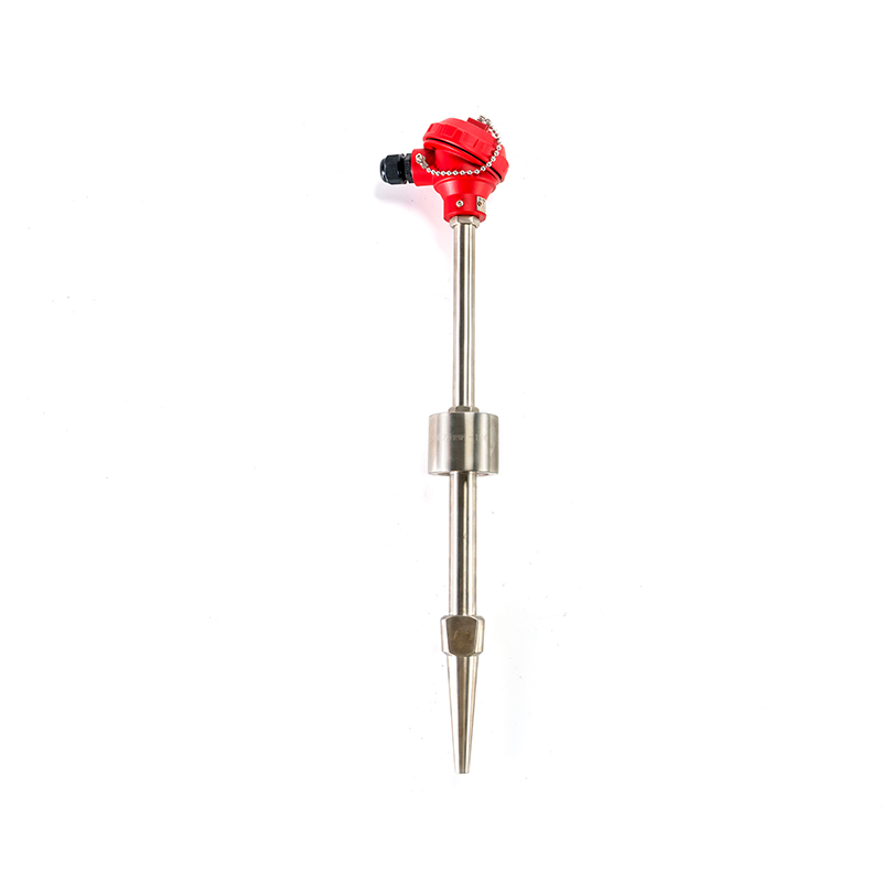
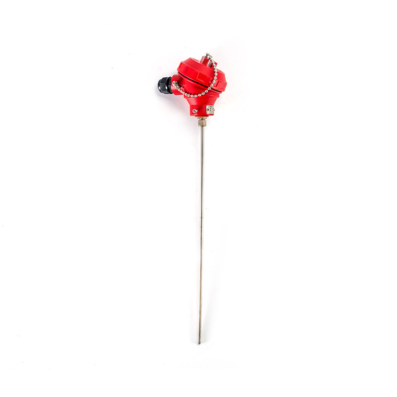 Dual Element Sheathed RTD for Redundant WiringThis compact mineral-insulated RTD offers two sensing elements in a flexible sheath, supporting redundant wiring without extra thermowells. Its fast response suits transmitter mounting and improves thermal measurement availability.View Product →
Redundant dual element RTD wiring is a proven way to improve thermal measurement availability without adding a second thermowell. In safety-instrumented functions, the second element can be used as a separate layer of protection, but only if the wiring is also redundant.
Start with the sensor junction head. Use two separate terminal rows, one for element one and one for element two, with a grounded shield barrier between them if possible. Run each element's leads in separate cables to the marshalling cabinet. Avoid running both elements through the same multicore cable because a cable fire or physical damage could remove both signals at once.
In the cabinet, assign element one to the basic process control system and element two to the safety system. This separation provides functional diversity. Some plants also connect element one to a redundant PLC input and element two to a separate vibration monitor for supervised logic.
Because both elements share the same sensing tip, they usually read almost the same temperature. A deviation alarm of 2 °C to 5 °C is typical for a healthy dual element RTD. If the deviation grows, it signals sensor drift, moisture ingress, or lead wire damage before either element fails completely.
For hot standby applications, the DCS or safety logic should continuously monitor both inputs and automatically switch to the healthy element when the active one fails. The switching logic must be tested at least once during commissioning and after any major instrument overhaul.
Sometimes engineers ask whether it is better to install one dual element RTD or two individual RTDs in separate thermowells. The answer depends on the process bore availability, response time, cost, and required independence.
| Factor | Dual Element RTD | Two Separate RTDs |
|---|---|---|
| Process penetration | One thermowell | Two thermowells or bore holes |
| Mechanical independence | Shared sheath/housing | Fully independent |
| Installation cost | Lower | Higher |
| Response speed | Similar if both elements in same bore | Can differ by insertion depth |
| Redundancy quality | Good for electrical/electronic faults | Better for mechanical damage |
| Maintenance flexibility | Remove one unit to replace both elements | Replace one sensor while other keeps measuring |
| Typical application | Fan bearing, motor winding, heat exchanger | Furnace section temperature comparison |
If you can install two separate thermowells, you get a higher level of physical diversity because a single mechanical impact cannot damage both sensors at the same time. This is sometimes required for severe service applications or when predictive maintenance programs need to replace sensors online.
If the process only permits one nozzle or thermowell, the dual element RTD is the practical answer. It is also an excellent choice for retrofits because you can replace a single element sensor without modifying the process connection.
Some users ask whether a dual element RTD is less accurate than a single element because the two elements might not be exactly identical. In practice, quality manufacturers match both elements to the same tolerance class. The IEC 60751 standard permits a maximum deviation for Class A and Class B, and good dual element sensors maintain both elements within that band.
Dual element RTDs are available in several physical constructions. The right choice depends on the process pressure, temperature, vibration, chemical attack, and installation requirements. You can often request a dual element configuration in a standard assemble RTD, a sheathed RTD, an explosion-proof RTD, or a multipoint design.
| Construction | Key features | Best for |
|---|---|---|
| Assemble RTD | Terminal head, threaded process connection, replaceable insert | General industrial process measurement |
| Sheathed RTD | Flexible mineral-insulated cable, small diameter | Machine bearings, hydraulic systems, limited space |
| Explosion-proof RTD | Flameproof enclosure, certified for hazardous areas | Oil, gas, chemical plants |
| Abrasion-resistant RTD | Hardened thermowell coating | Erosive or high-velocity media |
| Anti-corrosion RTD | PTFE or special alloy wetted parts | Acidic or alkaline process streams |
| Multipoint explosion-proof RTD | Multiple dual elements at different insertion lengths | Storage tanks, reactors |
The assemble RTD is the most common construction for general-purpose dual element wiring. It uses a threaded or flanged connection, a spring-loaded insert, and a cast iron or aluminum terminal head. That gives you enough space for two three-wire elements and two head-mounted transmitters.
For vibration-sensitive areas, a sheathed RTD with a compact connection head is safer because it has a smaller moment arm and can withstand mechanical stress. Sheathed dual element elements are also faster in response, making them useful when thermal runaway must be detected quickly.
In hazardous areas, the dual element RTD must be installed in an explosion-proof enclosure or through an intrinsic safety barrier. The wiring rules follow the local area classification, not just the sensor’s IP rating. Always check the product certificate and the cable entry approval.
If the dual element RTD will be used for a redundant safety function, request a connector and terminal arrangement that prevents accidental cross-wiring between elements. Some manufacturers offer keyed connectors or colored terminal blocks for this purpose.
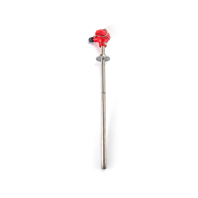
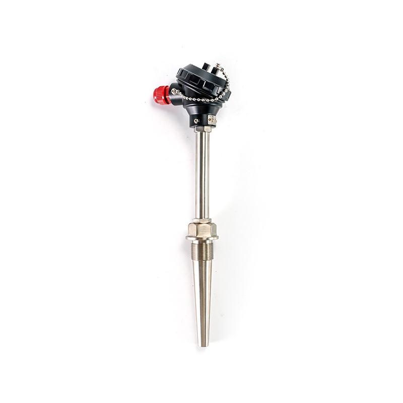 Assembly RTD for Process MonitoringA versatile sensor for direct liquid, gas, and surface temperature measurement, easily integrated with display and recording instruments. Its robust design suits process control and reliable real-time data acquisition.View Product →
Good dual element RTD wiring starts with good mechanical installation. The sensor should be fully inserted into the thermowell or process bore, and the terminal head should be oriented so cable entries point downward to reduce water ingress. Installation torque should follow the thread type; over-tightening a NPT or M20 connection can deform the sensor and shift the elements.
When you terminate the lead wires, avoid cutting them shorter than necessary. If a later wiring change is needed, enough spare length allows you to re-terminate. Use ferrules on stranded wires and do not leave loose strands that could short to the head casing.
| Field side Use mineral-insulated cable or flexible conduit with a sealed gland. Ground the shield at one end only. Keep the junction head clean and apply a small amount of non-hardening sealant if needed. |
Cabinet side Use separate cable entries for each element. Install surge protection if lightning or switching transients are expected. Label each wire with element number and terminal number. |
Maintain separation between RTD signal cables and power cables. The minimum recommended spacing is 12 inches from AC power lines, with crossing at right angles if unavoidable. This reduces induced noise that can cause erratic readings on a 3-wire connection.
For a dual element RTD in a thermowell, the two elements are usually located at the same depth. If you need two different temperature points in one reactor, choose a multipoint design rather than a standard dual element, because a standard dual element cannot measure two different locations.
After wiring, perform a simple continuity check between each element and its transmitter. Use a megger only with the transmitter disconnected, and never apply more than the rated insulation test voltage to the RTD elements.
Dual element RTDs must be tested on both elements, not just one. Many plants make the mistake of calibrating element one and assuming element two is identical. Even though both elements share the same housing, they can age differently due to thermal cycling, vibration, and moisture exposure.
The most reliable test is a precision resistance measurement at a reference temperature, such as an ice bath or a dry-block calibrator. Compare the measured resistance to the IEC 60751 table. For a Pt100 element, 0 °C should read approximately 100.00 ohms, and 100 °C should read approximately 138.51 ohms.
When performing a 3-wire calibration, the calibrator should use the same lead arrangement as the installed transmitter. Some portable calibrators compensate for lead resistance automatically, but you need to tell them which wire configuration you are using.
For critical safety applications, also perform a loop test through each transmitter and the control system input card. This verifies that the wiring from the sensor to the display is continuous and that the fail-safe state works when the element is disconnected.
If the two elements read correctly at room temperature but deviate at high temperature, check for mechanical strain or moisture in the sheath. A moisture-contaminated mineral insulation can cause shunt resistance that appears as a low reading at high temperature.
When a dual element RTD wiring loop shows an invalid reading, the fastest approach is to identify the faulty element and the fault type. An open circuit usually causes the transmitter to go upscale or downscale depending on its fail-safe setting. A short circuit can produce a low resistance reading, often near the cable resistance.
Begin by measuring both elements at the junction head. A healthy Pt100 element should show a resistance value consistent with ambient temperature. If one element reads open, the fault is inside the sensor or at its internal lead connection. If both elements read open, the problem is more likely in the shared cable gland or after severe mechanical damage.
Check the color coding of each lead before relying on a measurement. Some dual element sensors use the same wire colors for both elements, which makes it easy to assign the wrong pair. If the transmitter shows a reading that is exactly single-element resistance, you may have connected only one element and left the other open.
A common wiring error in 6-wire dual element RTDs is connecting the three leads of element one to a 3-wire transmitter while the transmitter input is configured for a single element but with the common lead from element two. This creates a high resistance reading because the circuit passes through both elements in series.
Regular maintenance should include tightening all screw terminals because thermal expansion can loosen them over time. Also inspect the junction head gasket. Moisture is the leading cause of insulation failure in RTD terminals, and it can affect both elements at different rates.
For troubleshooting support, keep a simple diagnostic table in the instrument folder with expected resistance values at common temperatures. This lets technicians quickly decide whether to replace the sensor or chase the wiring.
Dual element RTDs appear in almost every sector that needs reliable temperature measurement. The most common applications are motor and generator bearings, pump seals, compressor discharge lines, heat exchangers, power station feedwater, and chemical reactor skin temperatures.
In a motor bearing, the first element goes to the protection relay that trips the motor on high temperature, and the second element goes to a continuous temperature monitor. This avoids a single malfunctioning relay from taking the motor offline unexpectedly. The sensor is usually a small-diameter sheathed dual element RTD inserted into a drilled hole in the bearing housing.
In a heat exchanger, a dual element RTD is often installed in the outlet nozzle. One element feeds the control loop that adjusts cooling water flow; the second element feeds an energy monitoring system or a safety interlock. The same approach works on furnaces and fin-fan coolers.
In hazardous areas such as oil and gas facilities, an explosion-proof dual element RTD is required when the transmitter or terminals are located inside the classified zone. The flameproof enclosure prevents an internal electrical fault from igniting the surrounding atmosphere. Because the sensor has two elements, one can be used for process control and the other for a safety shutdown function that is independently certified.
For chemical plants with corrosive media, an anti-corrosion dual element RTD with a PTFE-lined thermowell provides two signals while protecting the platinum elements from acid attack. The same wiring principles apply, but the thermowell material and insertion length must be specified correctly.
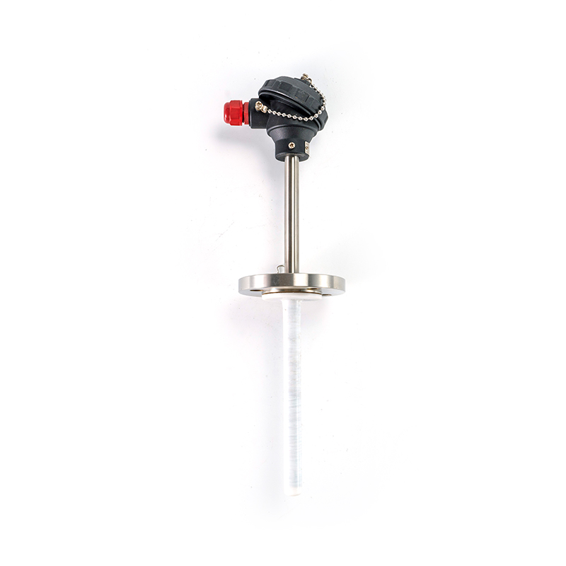
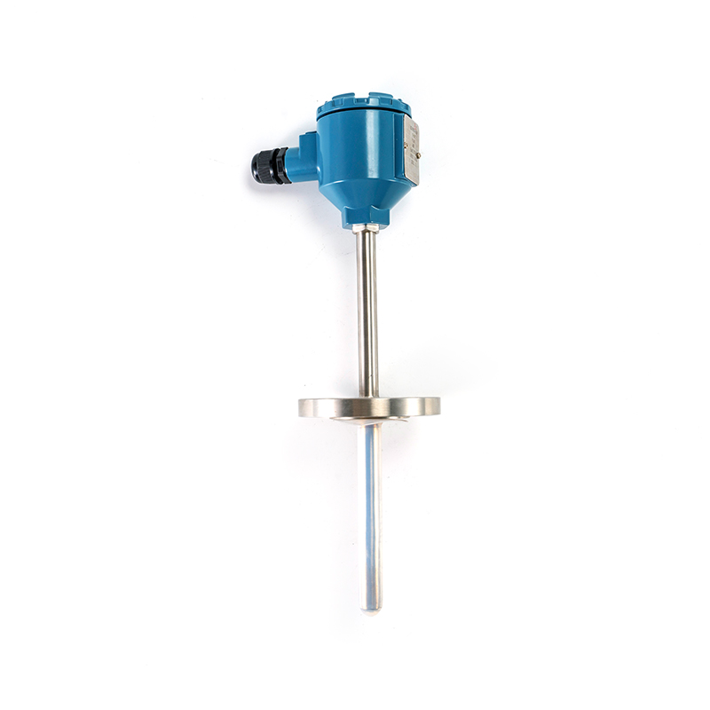 Explosion-proof RTD for Hazardous AreasDesigned for explosive environments with hydrocarbons, this sensor measures up to 1300°C with safety and precision. Appropriate for refineries and chemical plants needing secure temperature monitoring in volatile conditions.View Product →
| Application | Primary selection criterion | Wiring note |
|---|---|---|
| Bearing temperature | Small tip, fast response | Use 3-wire per element to avoid lead error |
| Heat exchanger outlet | Thermowell length, sealed connection | Separate cables to DCS and safety system |
| Hazardous area | Explosion-proof certificate | Follow intrinsic safety barrier requirements |
| Reactor skin | High temperature range, corrosion resistance | Use 4-wire for high-precision control |
When specifying a dual element RTD, provide the exact temperature range, process connection size, insertion depth, thermowell material, electrical termination type, and element tolerance class. A well-written specification saves installation time and reduces commissioning errors.
To better understand how dual element RTDs are applied in industrial plant maintenance, it is useful to look at the typical distribution of applications. The following chart is an illustrative breakdown based on field service experience and common instrument engineering practice.
It shows the share of dual element RTD installations by primary function: redundancy, separate display/control, temperature averaging, and calibration reference. This distribution helps plant engineers decide which wiring configuration is most worth mastering first.
The chart covers four broad functions. Redundant measurement dominates because safety systems increasingly require two independent sensors at one point. Separate display/control follows. Temperature averaging is more common in large air-cooled heat exchangers. Calibration reference is a niche but valuable use.
Because the data is not tied to a single industry, it should be treated as a planning reference rather than a certified statistics table. The important point is that the two elements of an RTD are not always wired for pure redundancy.
Let us now look at the horizontal bar chart.
The chart shows that redundant safety wiring is the largest category, but it is not the only reason to use a dual element sensor. The second largest category, control plus local display, is particularly common in rotating machinery, where an operator wants to read temperature locally while the DCS continues to control the process.
Averaged reading accounts for about 15 percent of installations. In these cases, two elements are not used independently; they are summed or averaged in a transmitter to represent the average temperature along a surface. This reduces the cost of installing multiple single-element sensors inside a large heater.
The calibration reference share, about 10 percent, is small but important. One element remains dedicated to a reference connection, while the second element is used for normal measurement. This lets technicians check the working element without opening the process.
From a wiring perspective, the chart reinforces that you should not assume every dual element RTD is meant for safety redundancy. Clarify the intended function first, because control plus display wiring can often tolerate a shorter cable run and lower cost, while redundant safety wiring requires full separation.
The distribution also suggests that three-wire connections are probably used in roughly 70 to 80 percent of dual element installations, since they are suitable for both redundancy and control applications. Four-wire connections are common in calibration reference installations and high-precision heat exchanger control.
If you design a new system, start by writing a simple function matrix for element one and element two. That exercise quickly reveals whether you need redundant transmitters, a single dual-input transmitter, or a specialized averaging transmitter.
Finally, the chart does not show the physical construction type. A plant may use 60 percent sheathed dual element RTDs on rotating equipment, 25 percent assemble type in general process piping, and 15 percent explosion-proof type in classified areas.
The exact percentages in your plant will vary, but the principle stays the same: define the role of each element before you pull cable, and document that role on the loop sheet.
What is the difference between a dual element RTD and a single element RTD?A dual element RTD contains two independent sensing elements in the same housing, while a single element RTD contains only one. With a dual element RTD, you can connect each element to a separate transmitter or safety system without adding a second process penetration. |
How many wires are in a dual element RTD?If each element uses a 2-wire connection, the dual element RTD has 4 wires. If each element uses a 3-wire connection, it has 6 wires. If each element uses a 4-wire connection, it has 8 wires. Most industrial dual element RTDs are 3-wire per element, or 6 wires total. |
Can a dual element RTD be connected to one transmitter?Yes, if the transmitter has two independent RTD inputs. Many modern multivariable transmitters support dual inputs. If your transmitter only has one input, you need two transmitters, one for each element. |
What is the proper dual element RTD wiring for redundancy?Wire element one to the primary control system and element two to the safety system using separate cables, separate terminals, and separate power supplies. The sensor elements must not share a common wire at any point. |
Is a dual element RTD more accurate than a single element RTD?Not automatically. Both elements are subject to the same tolerance requirements. The advantage of a dual element RTD is availability and redundancy, not higher absolute accuracy. If you need high accuracy, choose a 4-wire connection for both elements. |
Why does one element of my dual RTD read differently from the other?Small differences are normal, typically less than 0.5 °C at steady state. Larger differences can come from bad wiring, water in the connection head, or a failing element. Always measure both elements directly at the terminal head to isolate the fault. |
If you are still deciding between a single element and a dual element RTD, or you need help with a specific loop design, start with a short engineering consultation. A detailed sensor specification ensures that both elements are matched, insulated, and terminated exactly as your system requires.
Talk to a manufacturerIf you need help with dual element RTD wiring, process connections, or testing, contact our engineering team. We can help you choose the right sensor type and provide terminal diagrams for a clean installation. |
For a broader understanding of temperature sensor selection, read our industry guide on thermocouple types and selection. Although it focuses on thermocouples, the installation and wiring guidance is useful alongside RTD knowledge.
Read the thermocouple selection guide



 INQUIRY
 English
 عربى
عربى русский
 中文简体
中文简体